DLPU040C October 2016 – July 2024 DLP650LNIR , DLPC410
- 1
- Description
- Features
- 4
- 1Evaluation Module Overview
-
2Hardware
- 2.1
Key Components
- 2.1.1 Xilinx Virtex 5 APPSFPGA
- 2.1.2 DLPC410 - Digital Controller for DLP Discovery 4100 Chipset
- 2.1.3 DLPA200 - DMD Micromirror Driver
- 2.1.4 DLPR410 - Configuration PROM for DLPC410 Controller
- 2.1.5 APPSFPGA Flash Configuration PROM
- 2.1.6 DMD Connectors
- 2.1.7 USB Controller
- 2.1.8 50MHz Oscillator
- 2.1.9 DDR2 SODIMM Connector
- 2.1.10 Connectors
- 2.1.11 Battery
- 2.1.12 Power Supplies
- 2.2
Hardware Overview and Setup
- 2.2.1 Getting Started
- 2.2.2
User Connectors and I/O
- 2.2.2.1 J12 Input Power Connector
- 2.2.2.2 J18 Input Power Connector
- 2.2.2.3 J1 USB Connector Pinout
- 2.2.2.4 J3 USB GPIO
- 2.2.2.5 J6 GPIO_A Connector
- 2.2.2.6 J8 DLPC410 Mictor Connector
- 2.2.2.7 J9 USB/APPSFPGA Mictor Connector
- 2.2.2.8 J13 DMD Flex 1 Connector
- 2.2.2.9 J14 DMD Flex 2 Connector
- 2.2.2.10 J15 - DDR2 SODIMM Connector
- 2.2.2.11 J16, J17 EXP Connectors
- 2.2.2.12 H1 Xilinx FPGA JTAG Header
- 2.2.3 Configuration Jumpers
- 2.2.4 Switches
- 2.2.5 Power and Status LEDs
- 2.2.6 Test Points
- 2.1
Key Components
-
3Software
- 3.1 Overview
- 3.2 DLP Discovery 4100 Operation
- 3.3 Graphical User Interface
- 3.4 Script and Status Operations
- 3.5 DLPC410 Control Window
- 3.6 Test Patterns Window
- 3.7 About Box
- 3.8 Links
- 4Hardware Design Files
- 5Additional Information
- 6Related Documentation
- 7Revision History
3.2.1 Quick Start Guide on Operation
D4100 Explorer Windows Installer Error
During installation, user can be prompted with an error stating the installation did not complete correctly and that there was an error executing the post installation script. If this happens, then please follow the steps below:
- Uninstall the program
- Download and Install Microsoft 2010 Vcredist x86 version
- Reboot and re-install the DLPC410 GUI program
If there are no installation errors, then the following steps must be followed to operate the device:
- Install the software by executing the file D4100Explorer-2.0-windows-installer.exe. Install the software BEFORE connecting the USB cable to the DLPLCRC410EVM Controller Board. The setup program installs the software and driver INF files necessary for operation.
- A reboot is recommended before connecting the kit because some systems do not properly install the drivers if the system is not re-booted first.
- Connect the DLP with a USB 2.0 [mini-B to Type A] cable and apply power to the DLP Discovery 4100 Development Platform. The operating system detects the USB device and automatically install or prompt to install the driver.
- If automatic driver installation fails, go to Device Manager (Search for Device Manager in Windows search bar).
- Find the device and right click to select Update Driver Software.
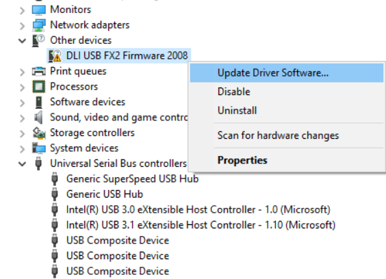 Figure 3-2 Updating Driver
Software
 - Select Browse my computer for driver software.
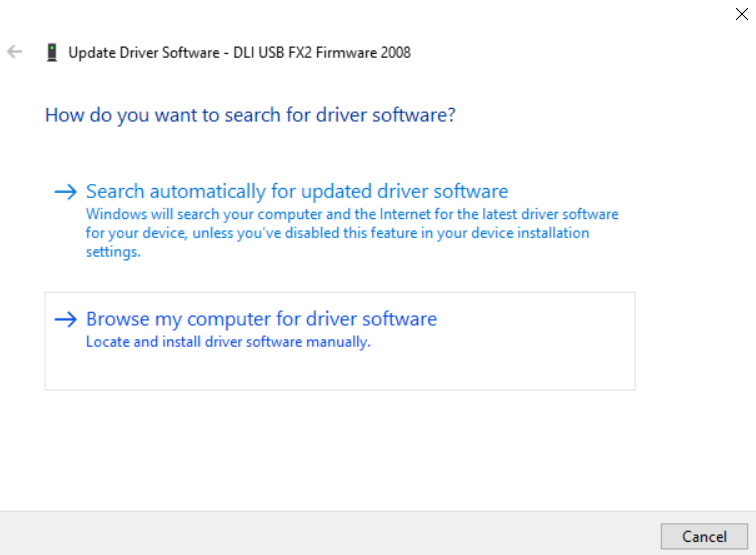 Figure 3-3 Browse for Driver
Software
 - Click Let me pick from a list of device drivers on my computer.
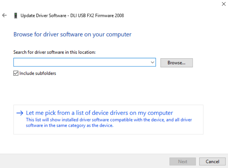 Figure 3-4 Pick from a list of
Device Drivers
 - Select Universal Serial Bus devices. Click
Next.
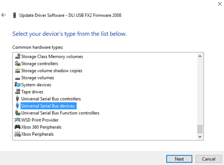 Figure 3-5 Select Universal
Serial Bus devices
 - Click on Have Disk.
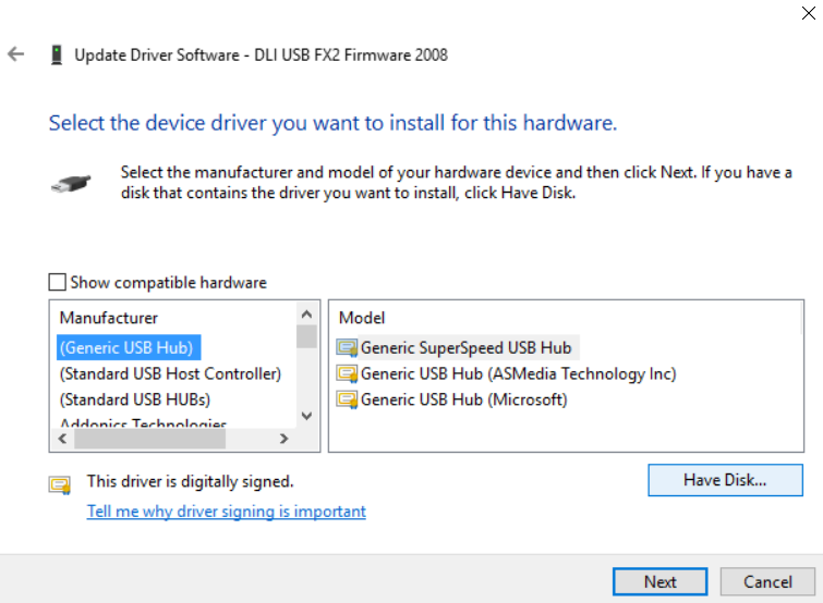 Figure 3-6 Have Disk
 - Browse to folder that contains the file
D4100-USB.inf. This file is found in <GUI Install
Directory>\Driver\. For example, in the Windows 10 64 bit operating
environment, navigate to C:\Program Files
(x86)\D4100Explorer\Driver\Win10\x64. Click OK.
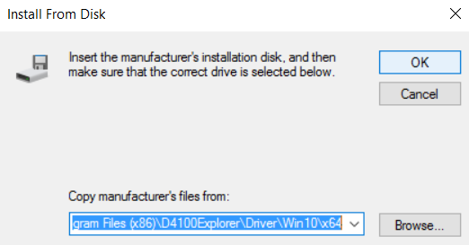 Figure 3-7 Browse for .inf
file
 - Click TI D4100 Explorer
- Click Next.
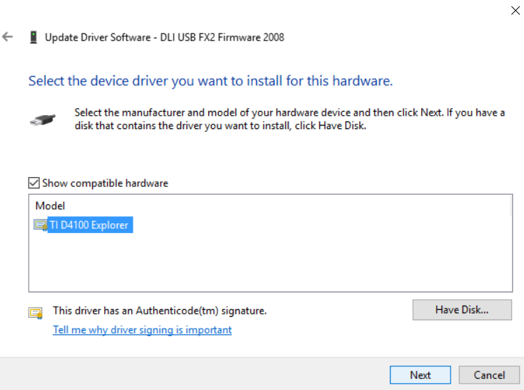 Figure 3-8 Select TI D4100
Explorer
 - Windows installs the driver.
- Click Close.
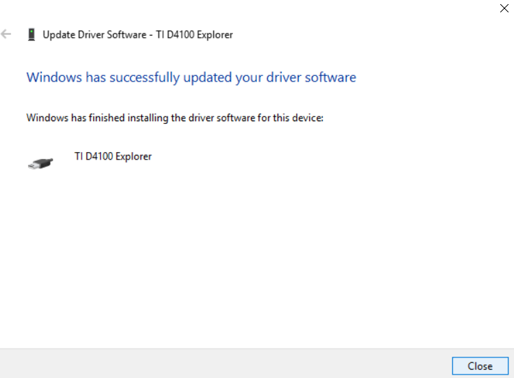 Figure 3-9 Driver Installation
Window
 - Verify driver installation in Device Manager window as shown in Figure 4-10.
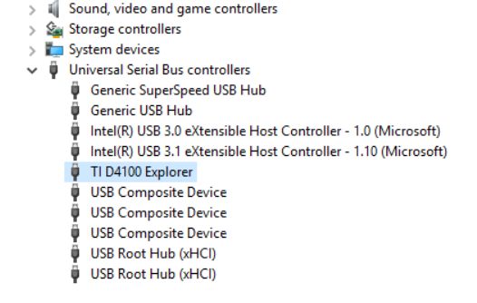 Figure 3-10 Verify Device
 - Start the DLP Discovery Explorer GUI from the Start/Texas Instruments/DLP Discovery 4100 Explorer menu.
- The software starts. The
USB connection status and DMD type is displayed in the lower left status panel
(Figure 4-11):
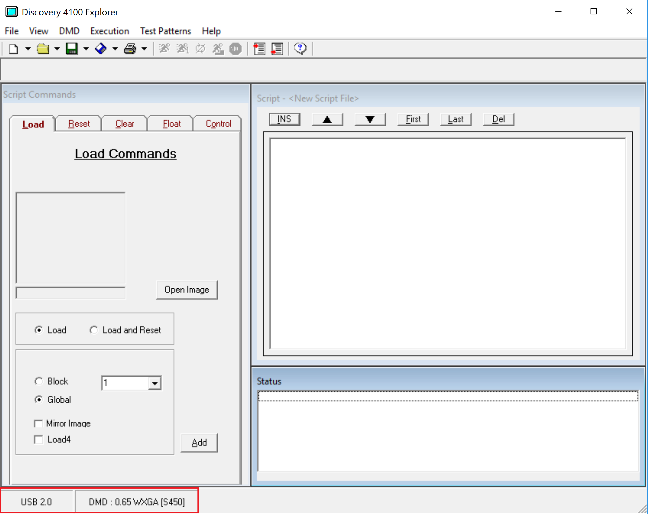 Figure 3-11 Discovery 4100 Explorer USB and DMD - Connection Status
 - Open an image using the Load Tab / Open Image button.
- Enter an image command in the script by selecting the desired options in the Load Tab button and clicking Add.
- Select and enter commands in the script. You select commands from any one of the command tabs on the Commands Window. Each tab contains a set of related commands and the options assigned to each command. Once you have selected the right combination of commands and options, enter the command into the script by clicking the Add button at the bottom of the command tab. Each tab has an Add button to enter that command into the script.
- Execute the script. Once the desired list of
commands has been entered into the Script Window, click the
 (Run) icon on the
toolbar to begin executing commands. Users can also choose to step through the
commands using the
  (Step) icon on the toolbar instead of running through them all. Users
can also use the Execution menu to perform the same functions. Use the
  (Stop) icon on the
toolbar to stop executing commands.
When the GUI is connected to a single Discovery EVM, moving the USB connector to a different Discovery EVM of different resolution does not scale the images already defined in the GUI scripts, and, therefore, can show up as incorrect on the DMD. The answer is to always restart the GUI software program after connecting to a different Discovery EVM.