DLPU101D December 2020 – July 2024 DLPC900
- 1
- Trademarks
- Read This First
- 1 About This Guide
- 2 Related Documentation from Texas Instruments
- 3 If You Need Assistance
- 4 DLP LightCrafter Single DLPC900 EVM Overview
- 5 Quick Start
-
6 Operating the
DLP LightCrafter Single DLPC900 EVM
- 6.1 DLP LightCrafter Single DLPC900 Control Software
- 6.2 PC Software
- 6.3 System Common Controls
- 6.4 System Settings
- 6.5 Video Mode
- 6.6
Pattern Modes
- 6.6.1 Menu Bar
- 6.6.2 Creating a Pattern Sequence in Pattern On-The-Fly Mode
- 6.6.3 Creating a Pattern Sequence in Pre-Stored Pattern Mode
- 6.6.4 Reordering a Pattern Sequence using the Edit LUT Feature
- 6.6.5 Creating a Pattern Sequence in Video Pattern Mode
- 6.6.6 Creating a Pattern Sequence With DMD Block Load
- 6.6.7 Pattern Settings
- 6.7 Batch Files
- 6.8 Peripherals
- 6.9 Firmware
- 6.10 Flash Device Parameters
- 6.11 JTAG Flash Programming
- 6.12 Programming an EDID
- 7 Connectors
- 8 Power Supply Requirements
- 9 Safety
- 10Revision History
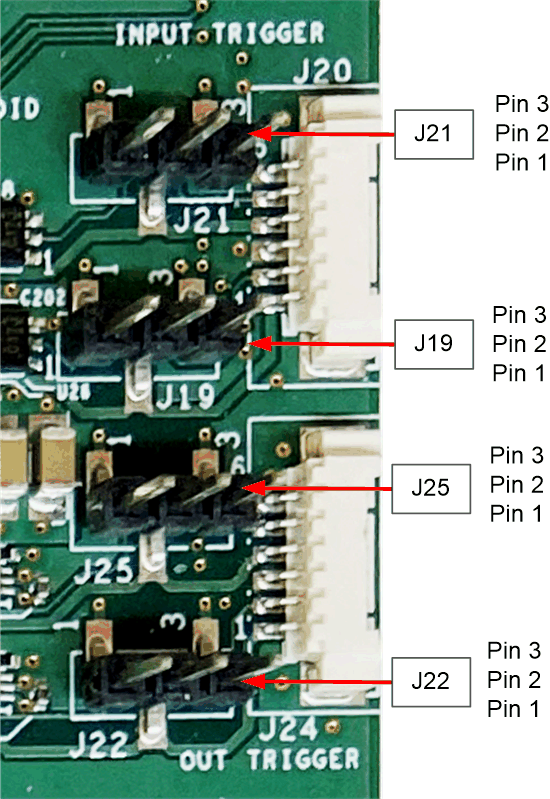
4.5.2 DLP LightCrafter Single DLPC900 Trigger Input and Output Voltage Selectors
The trigger inputs on J20 are inputs from external devices to control the pattern sequence. While trigger input 2 is high, trigger input 1 advances the pattern sequence to the next pattern that is waiting for a trigger input. See Section 6.6.4 for more information.
The trigger outputs on J24 are outputs to control external devices. While trigger output 1 frames the exposure time of the pattern, trigger output 2 pulses to mark the beginning of each pattern with a 19.4μs pulse.
Both input and output triggers have voltage level selectors. Use J19, J21, J22, and J25 to select the voltage as shown in Section 7.1 and Section 7.2. If no voltage is selected, then the onboard logic is not functional and any outgoing or incoming signals are not available.
 Figure 4-6 DLP LightCrafter Single DLPC900 EVM Trigger Voltage Level Selectors