DLPU106A March 2021 – October 2021 DLP3021-Q1
2.2.1 Formatter Subsystem
The formatter subsystem converts and translates image/video data stored in external flash memory through the FPGA based DMD controller into the Double Data Rate (DDR) interface format compatible with the DLP3021-Q1 data bus. The EVM offers two operating modes to specify what and how the image/video content is to be displayed: in a closed-loop stand-alone mode using the on-board MSP430 MCU, or through an external controller (such as the FTDI USB-to-SPI cable or Cheetah™ SPI Host Adapter) for GUI operation.
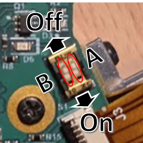
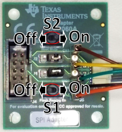
A DIP two-position switch at S1 on the DLP3021L1Q1EVM allows the user to physically set the operating mode of the formatter subsystem. The SPI Adapter board also has two physical switches (S1 and S2) to set the same operating modes. Figure 2-3 and Figure 2-4 show the default S1 switch state for Host Control operating mode for stand-alone operation, and the default switch state for Host Mute operating mode when the SPI Adapter Board is connected.
 Figure 2-3 Operating Mode Switches: Electronics
Board S1-A and S1-B Switches
  Figure 2-4 Operating Mode Switches: SPI Adapter
Board S1 and S2 Switches
Figure 2-4 Operating Mode Switches: SPI Adapter
Board S1 and S2 SwitchesSee Table 2-1 for the switch positions required of each operating mode.
|
Operating Mode |
DLP3021LEQ1EVM |
SPI Adapter Board |
LED State |
||
|---|---|---|---|---|---|
|
S1-A |
S1-B |
S1 |
S2 |
||
|
Host Mute |
Off |
On |
Off |
On |
Blue=ON, Amber=OFF, Green=ON |
|
Local Host Control |
Off |
Off |
Off |
Off |
Blue=OFF, Amber=OFF, Green=ON |
|
FPGA Programming |
On |
On |
On |
On |
Blue=ON, Amber=ON, Green=ON |
|
Undefined |
On |
Off |
On |
Off |
Blue=OFF, Amber=ON, Green=OFF |
A brief description of each operating mode is provided as follows:
-
Host Mute:
This mode allows direct read/writes to the DMD controller parameters. This is the
recommended operation mode of the EVM for initial development and debug purposes. The
FTDI cable and SPI Adapter board are required to run the EVM in this mode and bypass the
MSP430G2553-Q1 MCU on-board host controller. The DLP Control Program is the GUI used to
configure the DMD control parameters in this mode.
-
Local Host Control:
This mode allows the MSP430G2553-Q1 MCU on-board host controller to locally read/write
to the DMD controller. No additional hardware or GUI is required to run the EVM in this
mode because command execution by the MCU automatically starts after the EVM is
powered-up. This mode is recommended for demonstration purposes or system testing to
emulate the end-product module. The SPI Adapter board and FTDI cable are not required
for this operation mode.
-
FPGA Programming:
This mode allows the DMD controller to be reprogrammed using the DLP Composer GUI. The
FTDI cable and SPI Adapter board are required to run the EVM in this mode because the
flash program binary is uploaded from the PC to EVM through the FTDI cable. The light
engine will be disabled so that no content is displayed while the EVM is in this mode.
See Section 5.1.7 for details
on Flash Programming.
-
Undefined:
This mode is unsupported by the EVM and should not be used.
To allow the SPI Adapter board to set the operating mode, TI recommends the DLP3021LEQ1EVM electronics board S1 switches always be set to Local Host Control mode. This is because the On-state of either board will always override the Off-state of the other board. This setup will enable the use the more easily accessible S1 and S2 toggle switches of the SPI Adapter board to set the operating modes. When the SPI Adapter board is detached, the EVM will automatically start-up in the Local Host Control mode to allow the MSP430 to configure and run the EVM without intervention from an external controller such as the FTDI cable. When switching between operating modes, TI recommends that the EVM be fully power cycled to reset and apply the most recently set operating mode.