DLPU132A October 2023 – March 2024 DLPC964
- 1
- Description
- Get Started
- Features
- Applications
- 6
- 1Evaluation Module Overview
-
2Hardware
- 2.1 DLPLCRC964EVM Power Supply Requirements
- 2.2
DLPLCRC964EVM Connections
- 2.2.1 J1, J2 - HPC FMC Connector (Male)
- 2.2.2 J3 - Input Power
- 2.2.3 J4 - TestMux Connector
- 2.2.4 J6, J8 - I2C Address Selectors
- 2.2.5 J7 - JTAG Boundary Scan
- 2.2.6 J9 - Micro-B USB Connector
- 2.2.7 J10 - I2C Connector
- 2.2.8 J11 - 3.3V GPIO Connector
- 2.2.9 J12 - 1.8V GPIO Connector
- 2.2.10 J13, J14, J15, J16 - DMD EVM Board Flex Cable Connectors
- 2.2.11 J17 - DMD_DMux Connector
- 2.2.12 J18 - FanSink Connector
- 2.2.13 Switches
- 2.2.14 DLP LightCrafter DLPC964 LEDs
- 2.3 EVM Assembly
- 2.4 Quick Start
- 3Software
- 4Hardware Design Files
- 5Additional Information
- 6Related Documentation from Texas Instruments
- 7Revision History
3.1.5.3.2 Programming Apps FPGA by Flash
Follow the instructions below for loading the DLPC964 Apps binary onto the flash via a bitstream using Vivado Lab Solutions 2018.2:
Note: Click the link above to download Vivado Lab Solutions
2018.2. Once the web page is loaded, find the archived 2018.2 folder and then
navigate to the Vivado Lab Solutions 2018.2 downloadable link and download the
installation.
Note: The bitstream is always loaded onto the FPGA upon power-up
of the AMD EVM.
- Plug in the micro USB into the side of the AMD EVM and the other end into the computer running Vivado.
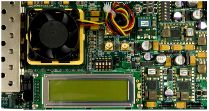
- Make sure to set SW11 to 00010 (1
= on, Position 1 → Position 5, left to right).
 Figure 3-19 FPGA Configuration
Mode
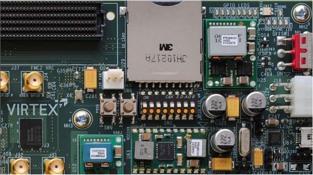
 - Set SW2
to 00000000 (1 = on, Position 1 → Position 8, left to right).
 Figure 3-20 GPIO Dip Switches
(VC707)
 - Start Vivado Lab Studios 2018.2 on the computer.
- Select Open Hardware Manager from the main window.
- Click open target located
in the top left of the hardware manager then Auto Connect.
- If the AMD EVM is the only FPGA plugged into the computer, then Vivado automatically connects to the AMD EVM. Otherwise, the process is slightly more involved.
- Right-click on the FPGA and select Add Configuration Memory Device.
- Find the Flash name mt28gu01gaax1e-bpi-x16 and click OK.
- Select OK again and select the
configuration file (appstop.mcs).
- Make sure all other settings match.
- Once setup, click OK. The programming can take a few minutes.
- Once completed, power cycle the AMD EVM, and the DLPC964 Apps Bitstream automatically loads onto the AMD EVM.