SBAA274A September 2018 – March 2023 ADS1118 , ADS1119 , ADS1120 , ADS112C04 , ADS112U04 , ADS1146 , ADS1147 , ADS1148 , ADS114S06 , ADS114S06B , ADS114S08 , ADS114S08B , ADS1219 , ADS1220 , ADS122C04 , ADS122U04 , ADS1246 , ADS1247 , ADS1248 , ADS124S06 , ADS124S08 , ADS125H02 , ADS1260 , ADS1261 , ADS1262 , ADS1263
- A Basic Guide to Thermocouple Measurements
- Trademarks
- 1Thermocouple Overview
-
2Thermocouple Measurement Circuits
- 2.1 Thermocouple Measurement With Pullup and Pulldown Bias Resistors
- 2.2 Thermocouple Measurement With Biasing Resistors Attached to the Negative Lead
- 2.3 Thermocouple Measurement With VBIAS for Sensor Biasing and Pullup Resistor
- 2.4 Thermocouple Measurement With VBIAS For Sensor Biasing and BOCS
- 2.5 Thermocouple Measurement With REFOUT Biasing and Pullup Resistor
- 2.6 Thermocouple Measurement With REFOUT Biasing and BOCS
- 2.7 Thermocouple Measurement With Bipolar Supplies And Ground Biasing
- 2.8 Cold-Junction Compensation Circuits
- 3Summary
- 4Revision History
1.4.2 Biasing the Thermocouple
After calculating the PGA gain, consider the PGA common-mode input range. Many PGAs are implemented similar to the front end of an instrumentation amplifier. This requires that the common-mode voltage of the input must be within the PGA range of operation. With increasing PGA gain, the common-mode input voltage is limited so that the amplifier output does not go into either the positive or negative supply rails. Consult the device data sheet for specific absolute or common-mode input voltage ranges. In most cases, setting the input to the mid-point of the analog supply voltages ensures the thermocouple is within the range of the PGA.
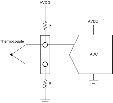
Thermocouples require biasing to set the sensor voltage DC operating point. There are a number of ways to bias the thermocouple. The most common method for thermocouple biasing is using large resistors tied to either end of the thermocouple as shown in Figure 1-5. The opposite end of the resistors are then tied to either supply. This method sets the thermocouple operating voltage at mid-supply assuming that the resistors are equal, and that the thermocouple voltage is relatively small.
 Figure 1-5 Resistor Biasing of a Thermocouple
Resistor values are generally chosen to be from 500 kΩ to 10 MΩ depending on the input current. Different ADCs have different magnitudes of input current. If the resistance is too high, the biasing current becomes too small compared to the ADC input current of the resistors. Consider the ADC input current when selecting resistor values as this may offset the bias point.
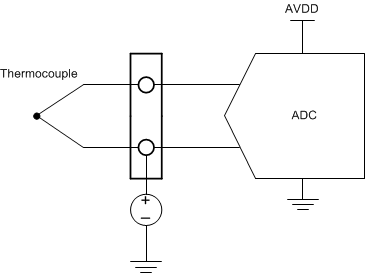
If the thermocouple leads are long, then resistor biasing may create additional error. Long resistive leads will react with the bias current to develop a voltage error in the measurement. In another biasing method, the negative thermocouple lead is connected to a known voltage source, as shown in Figure 1-6. Using a voltage source removes the bias current passing through the thermocouple. Only the ADC input current remains, which is usually orders of magnitude lower. In many cases, the ADC reference or an external reference may be used for biasing. Similarly, many ADCs have a VBIAS line that can be used to attach a specific analog input to a voltage generator through the input multiplexer of the ADC.
 Figure 1-6 Voltage Biasing of a Thermocouple
Similarly, if the ADC uses a bipolar supply, the negative thermocouple input can be tied to ground. Using the ground establishes the input at the mid-point of the supply and sets the bias point within the PGA input range.
Regardless, all of these methods establish a DC operating point for the thermocouple measurement. Many of the later sections of this application note discuss different circuit topologies for biasing the thermocouple.