SBAA274A September 2018 – March 2023 ADS1118 , ADS1119 , ADS1120 , ADS112C04 , ADS112U04 , ADS1146 , ADS1147 , ADS1148 , ADS114S06 , ADS114S06B , ADS114S08 , ADS114S08B , ADS1219 , ADS1220 , ADS122C04 , ADS122U04 , ADS1246 , ADS1247 , ADS1248 , ADS124S06 , ADS124S08 , ADS125H02 , ADS1260 , ADS1261 , ADS1262 , ADS1263
- A Basic Guide to Thermocouple Measurements
- Trademarks
- 1Thermocouple Overview
-
2Thermocouple Measurement Circuits
- 2.1 Thermocouple Measurement With Pullup and Pulldown Bias Resistors
- 2.2 Thermocouple Measurement With Biasing Resistors Attached to the Negative Lead
- 2.3 Thermocouple Measurement With VBIAS for Sensor Biasing and Pullup Resistor
- 2.4 Thermocouple Measurement With VBIAS For Sensor Biasing and BOCS
- 2.5 Thermocouple Measurement With REFOUT Biasing and Pullup Resistor
- 2.6 Thermocouple Measurement With REFOUT Biasing and BOCS
- 2.7 Thermocouple Measurement With Bipolar Supplies And Ground Biasing
- 2.8 Cold-Junction Compensation Circuits
- 3Summary
- 4Revision History
1.4.5 Conversion to Temperature
Conversion of data from the ADC requires both measurements of the thermocouple voltage and the cold-junction temperature. Often measurements of each are interleaved to ensure an accurate measurement of both. The flow diagram in Figure 1-7 shows the conversion method to determine the actual temperature of the thermocouple based on the ADC measurements.
 Figure 1-7 Thermocouple and Cold-Junction Measurement Conversion to Temperature
As previously mentioned the cold-junction temperature (TCJ) is first converted to a thermoelectric voltage (VCJ). This voltage is then added to the ADC measurement of the thermocouple voltage where
V = VCJ + VTC. This voltage sum is converted to temperature to determine the temperature of the thermocouple sensor.
Conversions from temperature to voltage or from voltage to temperature may be calculated though the polynomial equations explained in Section 1.2.2. Coefficients may be stored in the microcontroller to make these calculations for each ADC conversion.
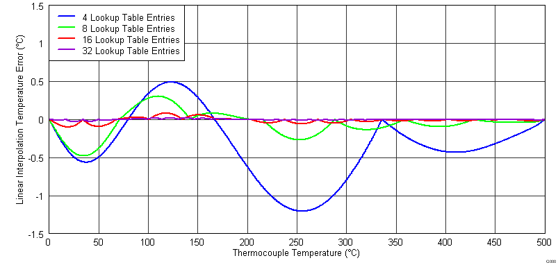
An alternative to processor-intensive calculations is to use lookup tables for a simple linear interpolation of these polynomials. Temperature and voltage ranges may be evenly broken up for making conversions. Precision Thermocouple Measurement with the ADS1118 describes using lookup tables with different numbers of table entries to calculate the thermocouple temperature. Figure 1-8 shows the conversion error that can be expected from linear interpolation using a lookup table for a K-type thermocouple from 0°C to +500°C. As the number of lookup table entries exceeds 16, the improvement in accuracy become smaller and smaller.
 Figure 1-8 Comparison of Interpolation Errors Using Various Lookup Tables