SBAA483 February 2021 ADS1120 , ADS112C04 , ADS112U04 , ADS114S06 , ADS114S06B , ADS114S08 , ADS114S08B , ADS1220 , ADS122C04 , ADS122U04 , ADS124S06 , ADS124S08 , ADS125H02 , ADS1260 , ADS1261 , ADS1262 , ADS1263
- Abstract
- Trademarks
- 1Introduction
- 2Features Used to Detect Wire Breaks in RTD Systems
- 3Wire-Break Detection Methods for Different RTD Configurations
- 4Settling Time Considerations for RTD Wire-Break Detection
- 5Summary
- A How Integrated PGA Rail Detection Helps Identify Wire Breaks
- B Pseudo-Code for RTD Wire-Break Detection
4 Settling Time Considerations for RTD Wire-Break Detection
One practical challenge in implementing the wire-break detection schemes discussed in this document is settling time resulting from analog filters on the measurement and reference input channels. All RTD configurations described in this document include generic low-pass RC filters on both sets of inputs to reduce noise, prevent aliasing, and limit current into the inputs in case of an overvoltage event. These figures do not include component values because the amount of filtering required for a specific system can vary greatly. To learn more about this topic, reference this short application note that discusses a general process for selecting low-pass RC filter component values.
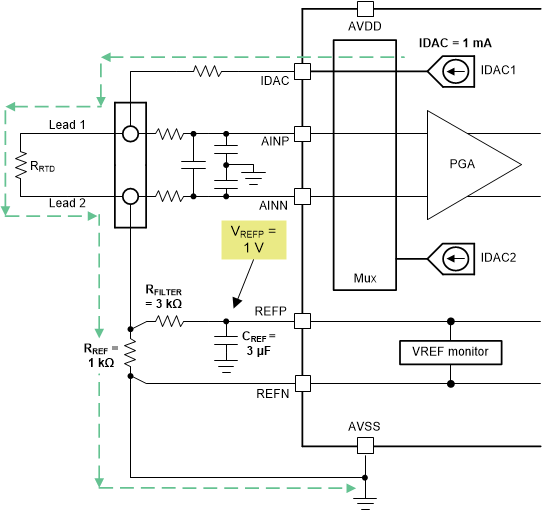
However, the component values selected for a design can have an impact on the overall system response time and therefore how quickly the circuit is able to respond to a fault. For example, Figure 4-1 shows how the IDAC current flows in a 2-wire RTD system with a low-side RREF. Sample component values are included in this specific figure, though these values were chosen to help explain settling time challenges and do not necessarily follow best design practices.
 Figure 4-1 Voltage at REFP in a 2-Wire
RTD During Normal Operation
Figure 4-1 Voltage at REFP in a 2-Wire
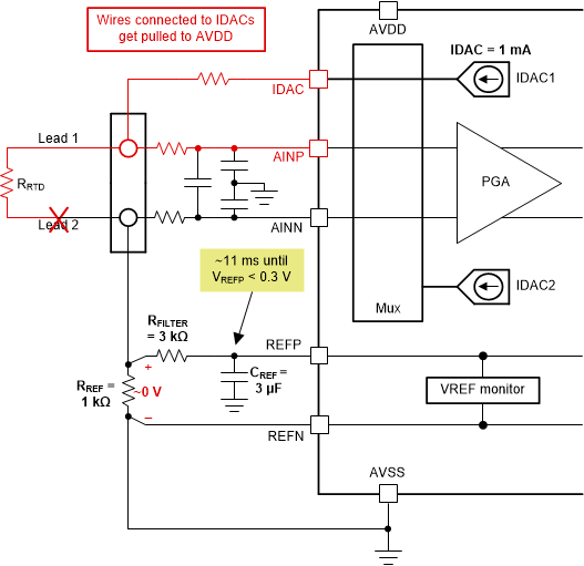
RTD During Normal OperationGiven the values shown in Figure 4-1, the voltage at REFP is equal to 1 V under normal operating conditions. When one of the RTD leads breaks, the IDAC current no longer flows through RREF such that the voltage across RREF is equal to 0 V, as illustrated in Figure 4-2.
 Figure 4-2 Extended Settling Time to
Reach VREF Monitor Threshold Because of CREF Discharge
Figure 4-2 Extended Settling Time to
Reach VREF Monitor Threshold Because of CREF DischargeAs Figure 4-2 also shows, some time is required to discharge capacitor CREF such that the voltage at REFP also drops to 0 V, or at least to a level that either trips the continuous VREF monitor or that can be accurately identified by the periodic VREF monitor. If the ADS124S08 is used in the system shown in Figure 4-2, approximately 11 milliseconds is required for VREFP to drop below the 300-mV detection threshold specified by the continuous VREF monitor integrated into this ADC. If the ADC sample rate is 1 kSPS (1 ms per conversion nominal), the external analog filter cannot settle fast enough for the ADC to identify a fault within one conversion.
Although waiting multiple conversions to identify a fault may be acceptable in some cases, consider the challenges that can arise if this delay occurred during the diagnostic cycle for a 4-wire RTD using a low-side RREF as described in Section 3.3.1. When switching the IDAC to lead 2 or lead 3 and checking the VREF monitor, the system can potentially have to wait ten conversions or more before a fault is identified. If the host controller is not set up to account for these delays, the system is not able to accurately and consistently detect RTD wire breaks.
Moreover, these settling time challenges can also be problematic when returning from a diagnostic measurement back to precision RTD measurements. If the IDACs are rerouted during the diagnostic cycle, large voltages can be present on the measurement and reference input capacitors that require multiple conversions to discharge. Again, if the host controller is not set up to account for these delays, the precision RTD measurement data can be invalid for several conversions.
Ultimately, consider the response time of any analog filtering on the measurement or reference inputs in order to design an effective RTD wire-break detection scheme.