SBAA583 july 2023 PCM1820 , PCM1820-Q1 , PCM1821 , PCM1821-Q1 , PCM1822 , PCM1822-Q1 , PCM3120-Q1 , PCM5120-Q1 , PCM6120-Q1 , TLV320ADC3120 , TLV320ADC5120 , TLV320ADC6120
- 1
- Abstract
- Trademarks
- 1Introduction
- 2AC Coupling Schemes
- 3DC Coupled Scheme
-
4Application Examples
- 4.1 Electret Condenser Microphone: Single Ended DC- Coupled Input
- 4.2 Electret Condenser Microphone: Single Ended AC Coupled Input
- 4.3 Selection of a Microphone
- 4.4 Condenser Microphone: Differential DC-Coupled Input
- 4.5 Condenser Microphone: Differential AC-Coupled Input
- 4.6 MEMS Microphone: Differential AC Coupled Input
- 4.7 Circuit With No Offset and Response Down to DC
- 4.8 Improving SNR by Summing the Output of 2 ADC Channels
- 4.9 Measure a High Voltage Waveform (+-50 V)
- 4.10 I2C Listing
- 5Summary
- 6References
4.10 I2C Listing
Condenser Microphone: Single Ended DC Coupled Input
The circuit below is of a DC coupled condenser microphone. A MicBias of 3.3 V is setup and a biasing resistor of 3 k is used setting up a Static DC level of 1.375 V on INxP pin. AVDD is 3.3 V. Sound signals picked up by the microphone create variations over this static DC bias.
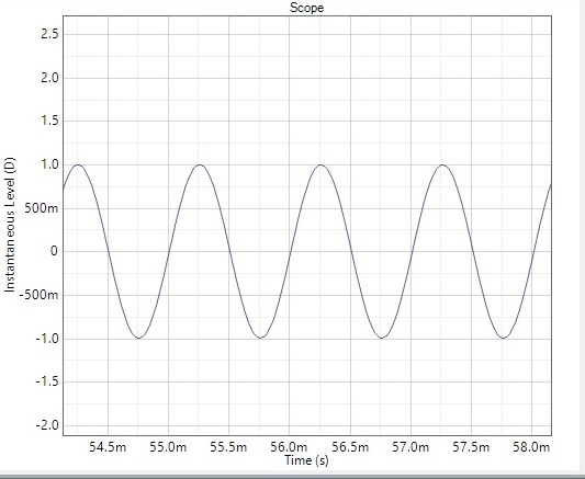
The high pass filter is used to remove the static DC level from the digital output. The digital output capture shown below is for a 1-Vrms input riding over a DC bias of 1.375 V.
 Figure 4-18 Single Ended DC Coupled
Microphone Circuit
 Figure 4-19 Digital Output Capture (Vin =
1 VRMS)
Figure 4-19 Digital Output Capture (Vin =
1 VRMS)Input Timing: 32 bit TDM, FSYNC = 48-kHz, BCLK = 12.288 Mhz.
w 9c 00 00 # Select Page 0
w 9c 01 01 # Reset Device
# 1mS Delay.
w 9c 00 00 # Select Page 0
w 9c 02 81 # Wake up and Enable AREG
w 9c 05 15 # ASI Channel configuration
w 9c 0c 01
w 9c 0d 02
w 9c 0e 03
w 9c 3b 60 # MicBias = 3.3 V
w 9c 3c b4 # Channel 1 configuration
w 9c 41 b4 # Channel 2 configuration
w 9c 74 c0 # input and output Configuration
# High pass filter coefficients
w 9c 49 e6
w 9c 4a 48
w 9c 4b c6
w 9c 4c 80
w 9c 4d 19
w 9c 4e b7
w 9c 4f 3a
w 9c 50 7f
w 9c 51 cc
w 9c 52 91
w 9c 53 8b
w 9c 00 06 # Select page 6
w 9c 1d 04
w 9c 1e b0
w 9c 7e 2d
w 9c 00 00 # Power up/down
w 9c 75 E0Condenser Microphone: Differential DC Coupled Input
The circuit below is of a differential DC-coupled condenser microphone. A mic bias of 3.3 V is setup and biasing resistors R of 1.1 K is used setting up a static DC level of 2.25-V on INxP and 0.75 V on INxM pin. AVDD is 3.3 V. Sound signals picked up by the microphone create variations over these static DC bias levels.
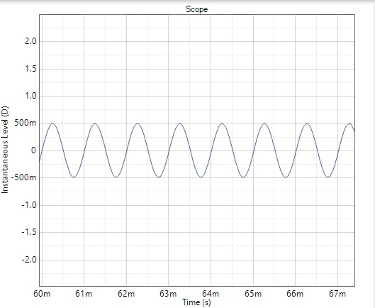
The high pass filter is used to remove the static DC level from the digital output. The digital output capture shown below is for a 1-Vrms differential input.
 Figure 4-20 Differential DC Coupled Circuit for Condenser Mic
 Figure 4-21 Digital Capture (Analog Differential Input of 1 Vrms)
Input Timing: 32 bit TDM, FSYNC = 48-kHz, BCLK = 12.288 Mhz.
w 9c 00 00 #Select Page 0
w 9c 01 01 # Reset Device
# 1mS Delay
w 9c 00 00 # Select Page 0
w 9c 02 81 # Wake up and Enable AREG
w 9c 05 15
w 9c 0c 01 # ASI Channel configuration
w 9c 0d 02
w 9c 0e 03
9c 3b 60 # MicBias = 3.3 V
w 9c 3c 90 # Channel 1 configuration
w 9c 41 90 # Channel 2 configuration
w 9c 74 c0 # input and output Configuration
w 9c 00 04 # Select page 4
# High pass filter coefficients
w 9c 49 e6
w 9c 4a 48
w 9c 4b c6
w 9c 4c 80
w 9c 4d 19
w 9c 4e b7
w 9c 4f 3a
w 9c 50 7f
w 9c 51 cc
w 9c 52 91
w 9c 53 8b
w 9c 00 06 # Select page 6
w 9c 1d 04
w 9c 1e b0
w 9c 7e 2d
w 9c 00 00 # Select page 0
w 9c 75 E0