SBAU141A January   2009  – April 2024 PCM2912A


  1.   1
  2.   Description
  3.   Get Started
  4.   Features
  5.   Applications
  6.   6
  7. 1Evaluation Module Overview
    1. 1.1 Introduction
    2. 1.2 Kit Contents
    3. 1.3 Specification
    4. 1.4 Device Information
  8. 2Hardware
    1. 2.1 Pin Assignments and Terminal Functions
    2. 2.2 Interface and Connections
  9. 3Software
    1. 3.1 Software Setup Guide
      1. 3.1.1 Basic Operating Setup for Windows 10
        1. 3.1.1.1 Basic Setup Before Evaluation
        2. 3.1.1.2 Volume and Mute Settings
        3. 3.1.1.3 Sampling Frequency
      2. 3.1.2 Basic Operating Setup for Mac OS
        1. 3.1.2.1 Basic Setup Before Evaluation
        2. 3.1.2.2 Volume Settings
        3. 3.1.2.3 Sampling Frequency
  10. 4Implementation Results
    1. 4.1 Evaluation Setup
    2. 4.2 Performance Data and Results
      1. 4.2.1 Measurements for Dynamic Characteristics
      2. 4.2.2 Playback Performance
      3. 4.2.3 Recording Performance
  11. 5Hardware Design Files
    1. 5.1 Schematics
    2. 5.2 PCB Layout
    3. 5.3 Bill of Materials (BOM)
  12. 6Additional Information
    1. 6.1 Trademarks
  13. 7Related Documentation
  14. 8Revision History

PCB Layout

Figure 6-2 through Figure 6-3 illustrate the printed circuit board (PCB) layout for the DEM-PCM2912A EVM.
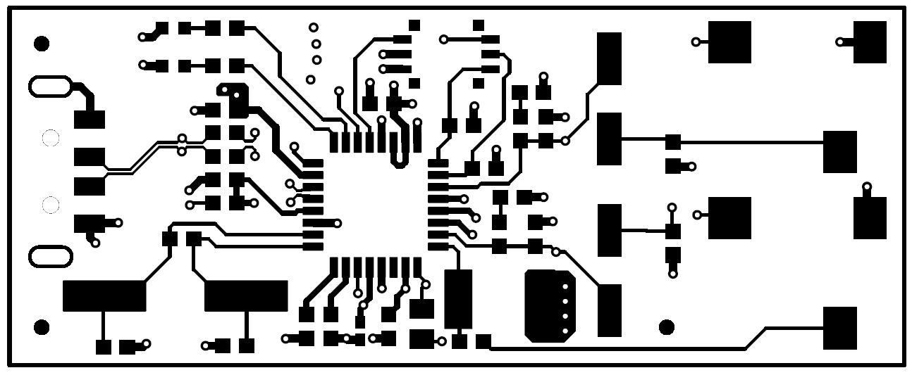
GUID-20240108-SS0I-XZTH-RCBB-XVTFVKKTX01W-low.png Figure 5-2 DEM-PCM2912A EVM Board Layout—Top Side
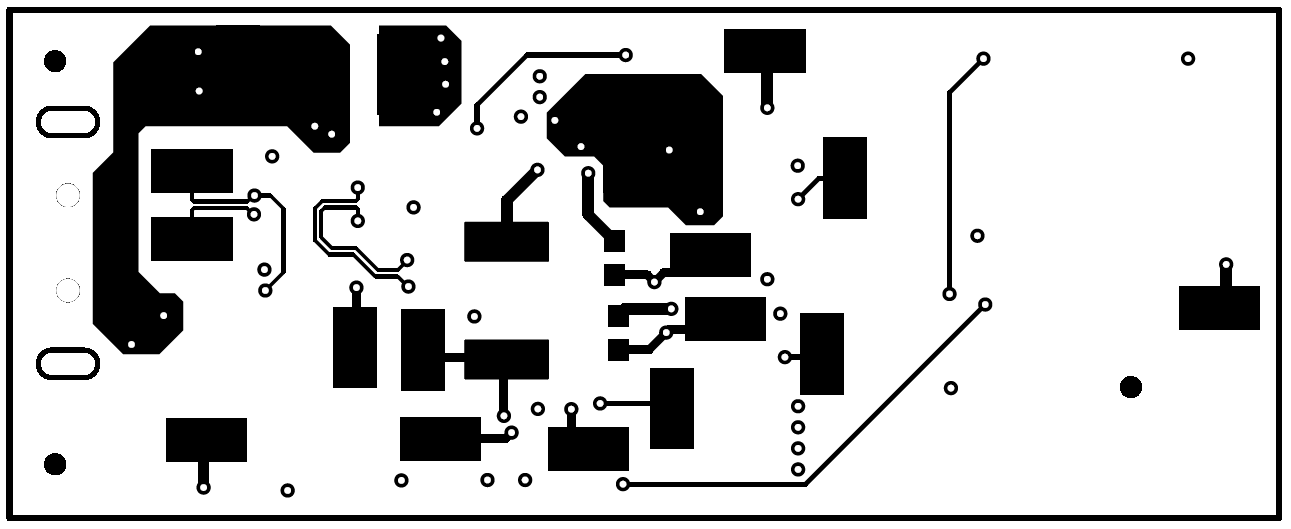
GUID-20240108-SS0I-VFZN-FGP1-QJFS5TP1HGQQ-low.png Figure 5-3 DEM-PCM2912A EVM Board Layout—Bottom Side