SBAU279 October 2020 ADS7038-Q1
- Trademarks
- 1Introduction
- 2ADS7038Q1EVM-PDK Overview
- 3ADS7038Q1EVM-PDK Initial Setup
- 4Input Signal-Conditioning Circuitry on the ADS7038Q1EVM
- 5Bill of Materials, Printed Circuit Board Layout, and Schematics
3.3.3 Data Capture Tab
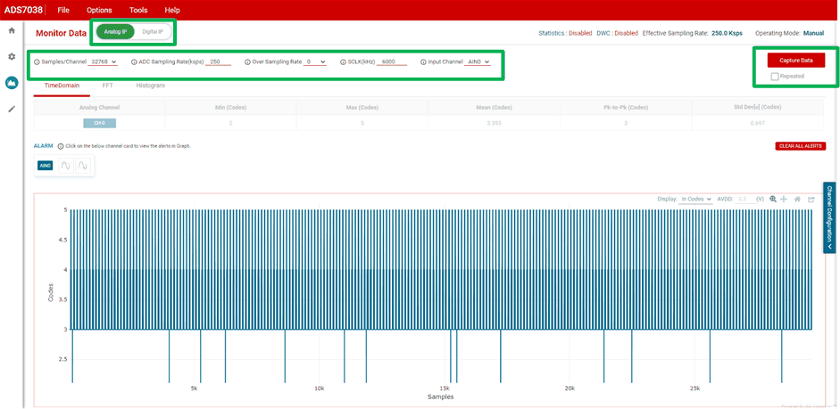
The data capture tab displays the conversion results of the sampled data of the enabled channels. As Figure 3-12 shows, clicking the red Capture Data button commences a sample data set. This page also displays the sampling mode configuration used to capture the data. There is also a checkmark option to repeatedly capture the sample size selected. This tab features two pages to display both the analog input and the digital inputs:
Analog Inputs: The sample and conversion results for each enabled analog input is displayed in this page. The results can be displayed in three methods: time domain, Fast Fourier transform (FFT), and histogram.
Digital Inputs: The enabled digital input channels are displayed in this page and can be polled for the current logic state.
 Figure 3-12 Data Capture tab.