SBAU420 March 2023
3.2.1.3.2 GUI Operation
To operate the GUI, follow these steps:
- Connect to and launch the GUI as described in GUID-E62C1C24-5C82-48A5-B32F-B7D98DD209BA.html#GUID-E62C1C24-5C82-48A5-B32F-B7D98DD209BA.
- With the EVM connected to the GUI, close the README.md file page. The text near the bottom-left hand corner of the GUI should read Hardware Connected (see #ID-924463B3-4652-43F2-E609-40AB7E3DA1B9).
 Figure 3-6 Hardware Connected
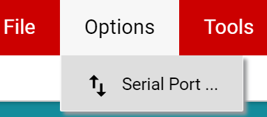
- If Hardware Connected does not show in the bottom-left hand corner of the GUI, check different hardware COM ports under Options → Serial Port (see #ID-D3E572A7-88F1-4E0F-B5CD-82FDE75558EB).
 Figure 3-7 Change Serial Port
 - If the hardware still does not connect, make sure you are using the correct GUI/EVM combination.
- If Hardware Connected does not show in the bottom-left hand corner of the GUI, check different hardware COM ports under Options → Serial Port (see #ID-D3E572A7-88F1-4E0F-B5CD-82FDE75558EB).
- Click the Registers icon shown in #ID-D562E0FA-04F5-4758-DE09-A5C04185074F (also available on the left-side menu) to view the register map, change device settings, and enable automatic register read. Each die within the TMAG5170D may be configured independently using the device select, or both sensors can be configured under the same register settings (if desired). For questions about a register or register bit field, select the
 icon. For more questions about registers, check the data sheet.
  Figure 3-8 Registers Page Icon
 - Click the Plots icon to view and save graphical data from the results registers (see #ID-2FBE227F-5AB9-42A9-98C8-EB7DCA4B16C3). This is also available on the left-side menu.
 Figure 3-9 Plots Page Icon