SBOA400 July 2020 – MONTH TMCS1100 , TMCS1100-Q1 , TMCS1101 , TMCS1101-Q1 , TMCS1107 , TMCS1107-Q1 , TMCS1108 , TMCS1108-Q1
4 Measuring Junction Temperature
The absolute maximum ratings table specifically states that the upper bound for junction temperature is 150°C and further states that "stresses beyond those listed under Absolute Maximum Ratings may cause permanent damage to the device." Consequently, knowing the junction temperature is important for verifying whether the device will survive a given set of operating conditions. As junction refers to the die encased in the device package, thereby shielded from a typical optical or physical probe, this presents a challenge. Fortunately, by characterizing one of the device ESD diodes covered in the previous section , the junction temperature can be determined for a given load current.
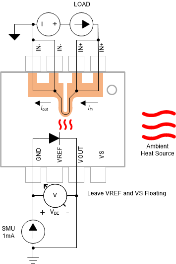
The method for measuring junction temperature for a given load is very similar to the method used for characterizing one of the internal ESD diodes. The key difference is that relating diode voltage to temperature with Equation 2 can now be leveraged to determine what temperature the junction experiences for a given load at a given ambient temperature. Figure 4-1 illustrates one possible test setup, in which heat generated from passing load current through the leadframe is monitored by the ESD diode forward biased from the GND to VOUT pins.
Step Summary
- Apply SMU positive terminal to device ground pin and SMU negative terminal to device VOUT pin.
- Source 1 mA of current to GND pin from source meter.
- Measure voltage across body diode, in this case GND to VOUT.
- Sweep DUT through series of load current levels. At minimum measure two current levels.
- Use the equation derived from diode characterization to determine load to junction temperature relationship.
 Figure 4-1 Junction Measurement Schematic