SBOA518 January 2022 TMCS1100 , TMCS1100-Q1 , TMCS1101 , TMCS1101-Q1 , TMCS1107 , TMCS1107-Q1 , TMCS1108 , TMCS1108-Q1
6.1 Shielding
Shielding utilizes the property of reluctance, which for magnetic fields is analogous to resistance for current. Magnetic fields route through the path of least reluctance. Inversely related to reluctance is permeability. Materials with high permeability have low reluctance and therefore are highly desirable for shielding, which actually serves to divert the magnetic field away from the Hall sensor. The material chosen, based on its permeability, must be of a certain thickness to ensure that it is capable of diverting the totality of the field away from the part, because shielding material is also capable of saturation. If the shielding material saturates, excess magnetic flux continues to pass through the material and exert influence on the sensors.
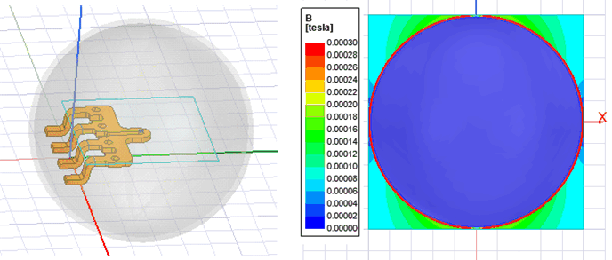
To better visualize how shielding works, an example of a shield and concentrator are provided in Figure 6-1 and Figure 6-2. In both images, there is a uniform field of several µT directed through the examined volume along the Z-axis.
The first figure shows the cross-sectional area of the XZ plane, and that the shell of the shield diverts a majority of the field, with the space internal to the sphere at much lower magnitudes of field strength than that diverted by the shield.
The second figure inserts a conical concentrator structure into the same field above and below the device. Here, the XZ cross section is also examined. The upper cone structure channels the majority of the field entering the base towards the cone tip where it then exits and passes into the tip of the bottom cone and continues to move downward. Note that such a structure is the dual to the shield of the first figure, and is not recommended as a shielding geometry. This also means that any wires or flux carrying components placed over the device may influence measurements, including while debugging, so ensure these types of devices are kept in check from the sensor.
 Figure 6-1 Spherical Shield Layout and
Simulated Field Deflection (Side View)
 Figure 6-2 Conical Concentrator Layout
and Simulated Field Concentration (Side View)
Figure 6-2 Conical Concentrator Layout
and Simulated Field Concentration (Side View)Note that for the illustration, a perfect spheroid is likely unattainable when manufacturing or choosing shield shapes, nor is completely enclosing the device as shown in the simulation. This image is meant as a concept for visualization, and certain geometries may work more effectively than others in a given system.
In summary, if shielding is chosen as a method for field mitigation, ensure that the correct material is chosen, that it is shaped appropriately, and it is sized to ensure proper field diversion.