SBOU318 July   2024 TRF1108


  1.   1
  2.   Description
  3.   Features
  4.   4
  5. 1Evaluation Module Overview
    1. 1.1 Introduction
    2. 1.2 Kit Contents
    3. 1.3 Specification
    4. 1.4 Device Information
  6. 2Hardware
    1. 2.1 General Usage Information
  7. 3Implementation Results
    1. 3.1 Test Setup Diagrams
      1. 3.1.1 S-Parameter Test Setup
      2. 3.1.2 Noise Figure Test Setup
      3. 3.1.3 Two-Tone OIP3 Test Setup
  8. 4Hardware Design Files
    1. 4.1 Schematic
    2. 4.2 PCB Layers
      1. 4.2.1 Stack-Up and Material
    3. 4.3 TRF1108 EVM Bill of Material
  9. 5Additional Information
    1. 5.1 Trademarks
  10. 6Related Documentation

PCB Layers

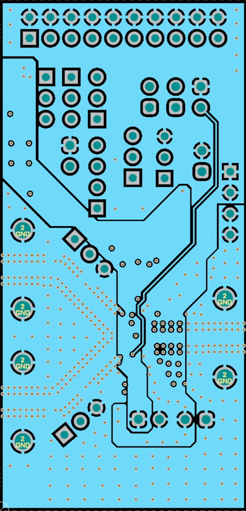
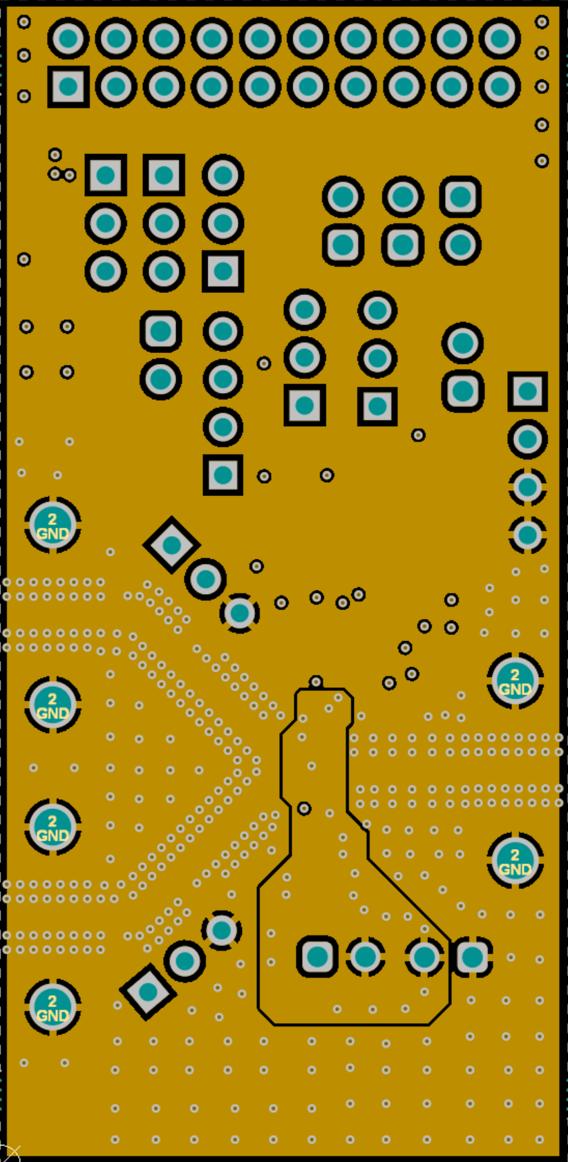
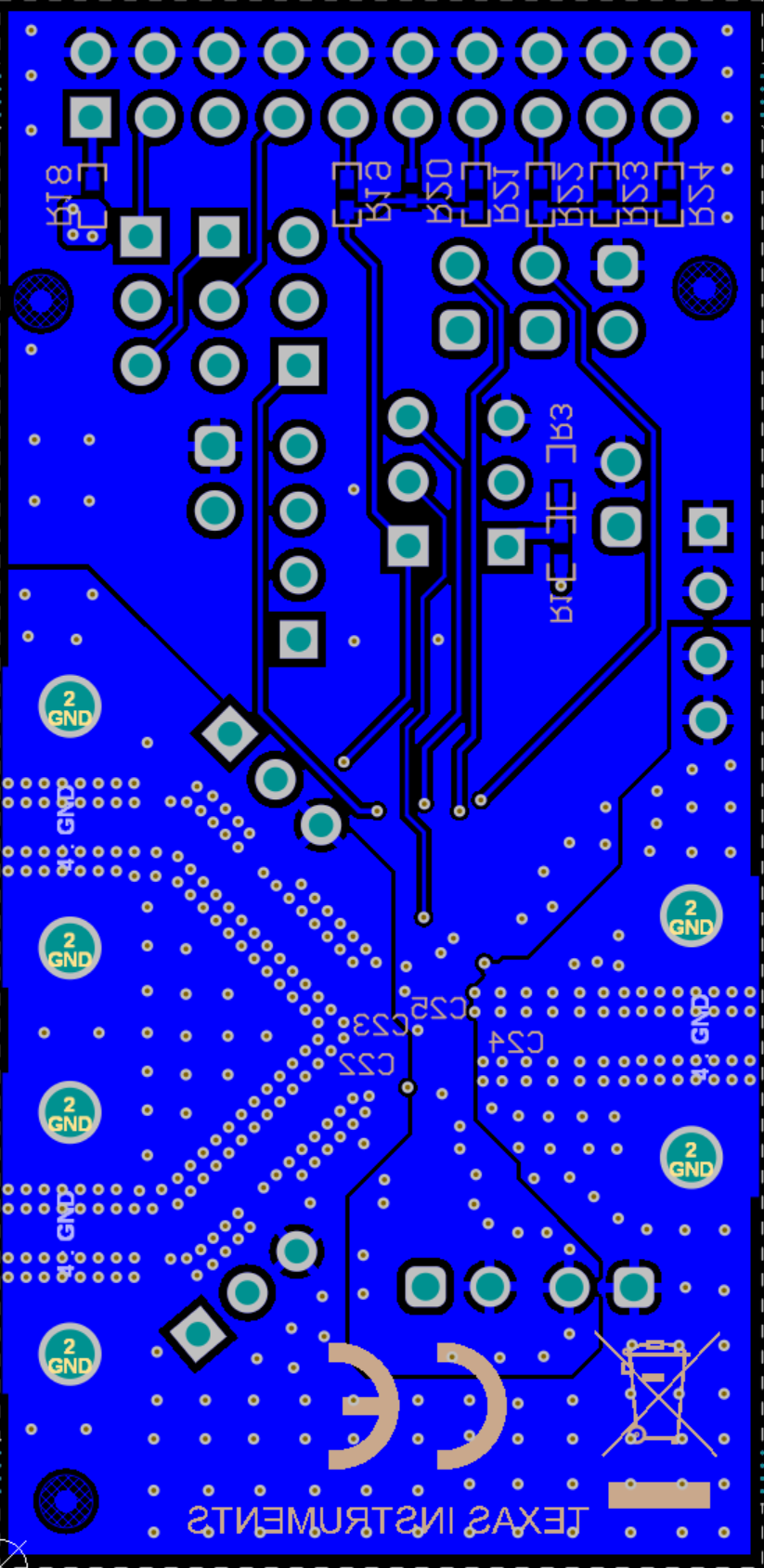
Figure 5-2 through Figure 5-5 illustrate the PCB layers for this EVM.
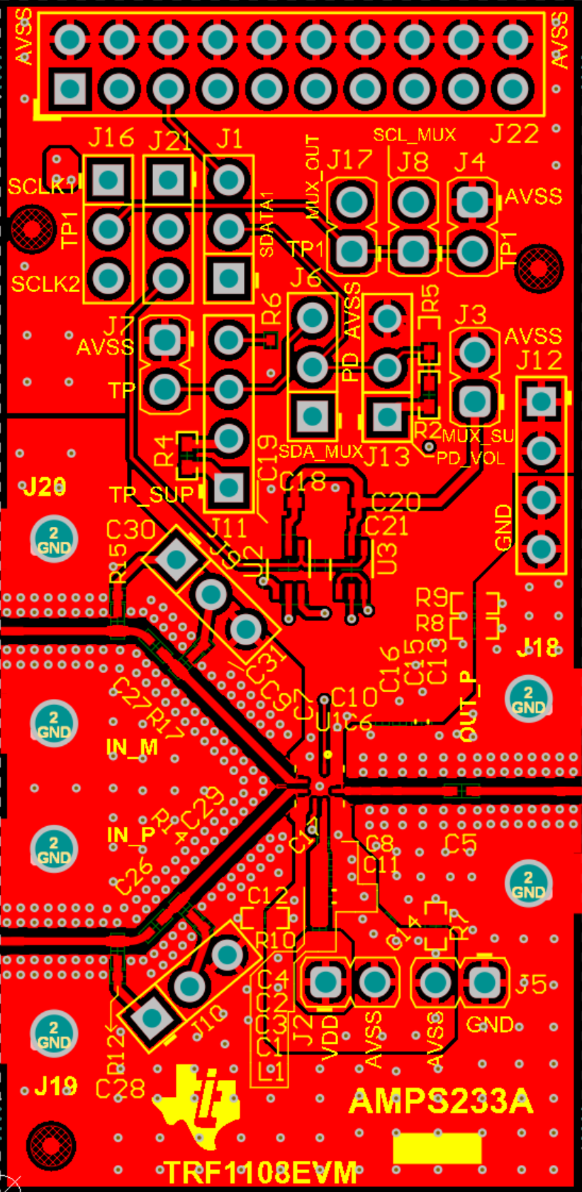
TRF1108EVM Top
                        LayerFigure 4-2 Top Layer
TRF1108EVM Layer
                        3Figure 4-4 Layer 3
TRF1108EVM Layer
                        2Figure 4-3 Layer 2
TRF1108EVM Bottom LayerFigure 4-5 Bottom Layer