SCDA046 January 2024 TMUX7308F , TMUX7309F , TMUX7348F , TMUX7349F , TMUX7411F , TMUX7412F , TMUX7413F , TMUX7436F , TMUX7462F
2 System Level Protection Explanation and Design Based on Fast Fault Recovery Time
To help system designers combat failure due to EFT burst and permanent miswiring, we outline considerations that are important in PLC communication design. First, PLC inputs and outputs are typically protected using TVS diodes either discrete ones or flat clamp diodes like TVS3301. These TVS diodes already clamp the very high burst transients. While TVS diodes can withstand bursts in the kV range, electronic components can not.
On the other hand, electronic circuits for PLC systems must be able to withstand permanent EFT burst pulses and permanent miswiring from external voltage sources. As TVS diodes are conducting under over-voltage conditions, they cannot handle a permanent over-voltage/under-voltage (OV/UV) condition. For analog output or current inputs where higher currents can flow, using a TVS diode with no protection switch introduces a challenge. For example, while burst clamping TVS diodes can trigger at a higher voltage like 36V, a permanent 24V DC into the output can potentially destroy PLC system electronics. A system designer can place a clamping diode that can clamp around 15V to protect a +/-15V supplied output. In case of a 24V miswiring the diode permanently conducts and shunts all the current the supply can deliver. This causes the diode to dissipate a huge amount of energy and eventually be destroyed. Introducing a protection switch solves this problem because the permanent DC miswiring voltage is blocked.
TVS diodes also must not impact analog signals with their leakage currents. This means the clamping voltage must be selected such that they are transparent to the signal and do not conduct within the OVP protection rating of a switch but clamp above this level to protect from burst. This defines the need for a protection switch that can handle permanent EFT burst pulses and can block permanent DC OV/UV conditions following TVS diodes.
Finally, to help maintain signal integrity during EFT burst, designers must select a protection switch with the proper fault recovery time. If the fault recovery time (trecover) of the protection switch on the signal link line exceeds the off-time (toff) between two pulses within a burst packet, then the system fails Criteria B which means the link discharges and the signal is lost (Figure 2-1). For EFT burst testing the time between two pulses within a burst packet are 10us or 200us depending on the selected repetition time.
 Figure 2-1 Link Discharged During Burst Testing With Too Long Recovery Time
To solve this problem, use a TI Fault Protected Multiplexer which has a fast-enough recovery time such that the link can be recharged between EFT pulses. TI Fault Protected Multiplexers have fault recovery times ranging from 1.1us to 1.6us at a +/-15V supply (Figure 2-2).
 Figure 2-2 Link Recharged During Burst Testing Fulfilling EFT Burst Test Criterion B
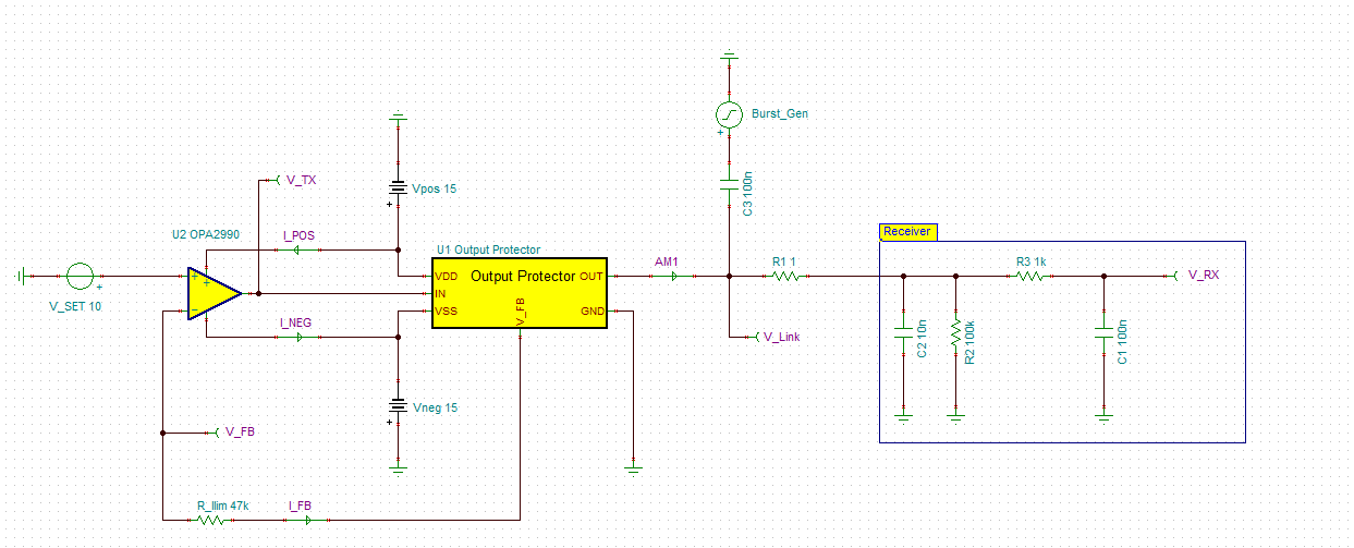
To see the expected results, we can also take a look at the Tina-TI model (Figure 2-3). This model represents a PLC communication system where a 10V signal is produced from the OPA990, sent through the Output Protector switch and then finally passed through the receiver also known as an analog output module. In addition, the burst generator is sending a 0 to 20V, 100kHz standard EFT pulse onto the signal line modeling a clamped pulse. The Output Protector has a fault recovery time of 2us.
 Figure 2-3 Tina-TI Model
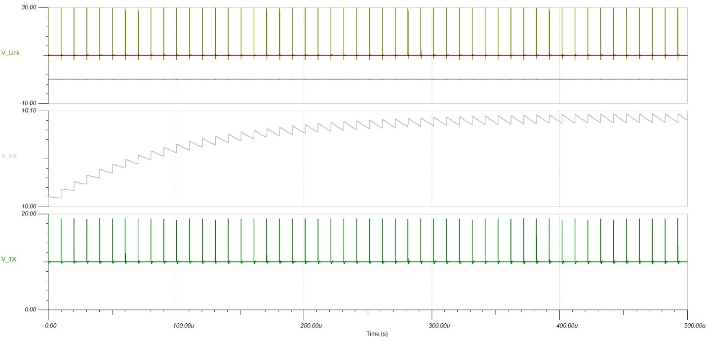
 Figure 2-4 Tina-TI Model Results
V_Link shows the burst pulse on top of the signal. V_TX is the output of the amplifier and V_RX is the analog output module. Looking at Figure 2-4, we can expect the fault-protected switch to reconnect the signal line between EFT pulses and the offset voltage error on the output is 100mV. A small voltage error of less than 100mV added to the 10V signal line link is what we expect when testing TI’s fault-protected devices with standard EFT pulses.