SCEU031B August 2024 – October 2024 TPLD801
PRODUCTION DATA
2.1.6 SW or LED Testing Blocks
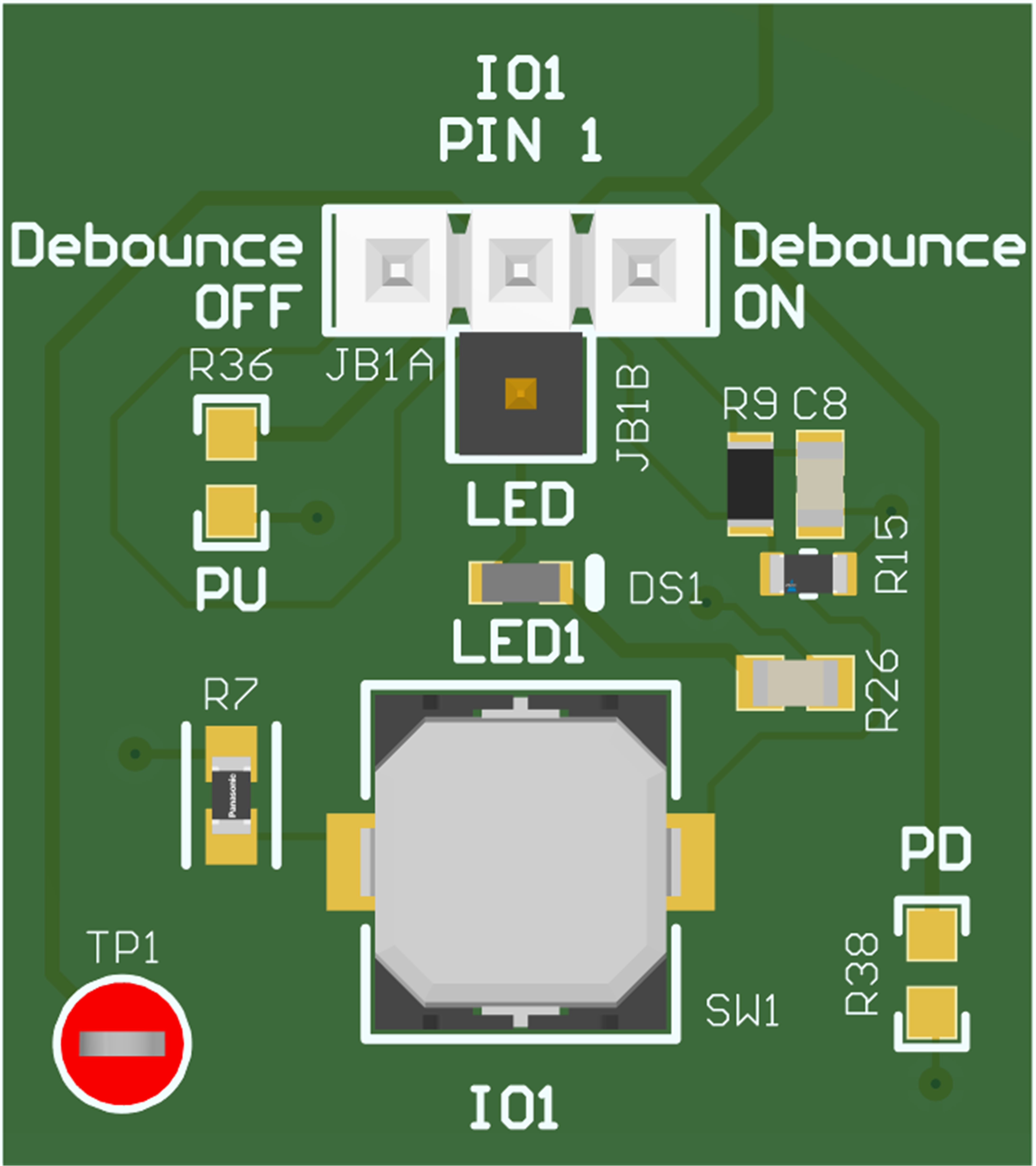
Each IO pin of the TPLD801DRL except for the GPI pin (pin 7) is connected to a SW/LED testing block. Each SW/LED block consists of a 4-position header that can be connected to a tactile switch with an optional debounce circuit, or to an LED. One side of the 4-position header, labeled OFF, connects directly to the switch output, and the other side of the 4-position header, labeled ON, connects to a debounce circuit leading to the switch output. The pin labeled LED connects to an LED. The middle pin of the header connects to the corresponding TPLD pin. To connect directly to the switch output, place a shunt between the middle pin of the header and the OFF pin. To connect to the debounce circuit, place a shunt between the middle pin of the header and the OFF pin. To connect to the LED, place a shunt between the middle pin of the header and the LED pin. If no shunt is placed between any set of pins, then the TPLD pin is floating.
Each SW/LED Block has soldering spots for optional pull-up and pull-down resistors. These are initially de-populated and are labeled PU and PD, respectively.
 Figure 2-3 Switch/LED Blocks