SCLA068 August 2024 TPLD1201 , TPLD1201-Q1 , TPLD1202 , TPLD1202-Q1 , TPLD801 , TPLD801-Q1
Introduction
Optical sensing is useful in a wide variety of applications, from detecting liquid levels in industrial settings to object recognition in machine learning environments. These systems are typically comprised of a photodiode, used to detect light connected to an amplifier, which feeds the output of the photodiode into an ADC or comparator for analog-to-digital conversion. After this conversion, the signal is fed to some format of configurable logic (such as a CPLD or FPGA) or a microcontroller for processing. Such configurations are displayed in Figure 1. The built-in analog comparators on TPLD1201 devices allow for the devices to directly receive the amplified output from the photodiode, removing the need for an ADC or external analog comparator, as shown in Figure 2.
Occupancy-based control of lighting systems is becoming increasingly popular to save energy in empty spaces or when ambient light is sufficient. This article explores utilizing TPLD devices, in conjunction with an optical sensor, to implement a smart occupancy lighting system. The TPLD1201 receives an amplified photodiode signal and provides an enable signal to a relay or load switch that is controlling power to a lighting array.
 Figure 1 Typical Photodiode Sensing
System
 Figure 2 Photodiode Sensing with
TPLD1201
Figure 2 Photodiode Sensing with
TPLD1201Design Considerations
- Add a decoupling capacitor between VCC and GND. Typical values are 0.1μF or 1μF. The capacitor must be placed physically close to the device.
- For better performance, the capacitive load at each output must not exceed 50pF. Verify that traces, from the device outputs, to the relay/load switch inputs are not overtly long to avoid loading too much capacitance.
- The resistive load at the output must be greater than (VCC / IDC) Ω to prevent the absolute maximum current output ratings being violated. This load depends on the type of output structure the output pins are programmed for (TPLD1201 pins can be programmed as push-pull or open-drain outputs, with gains of 1X or 2X).
- If the output pins of the device are configured as open-drain, NMOS or PMOS, chose appropriate pulldown/pullup resistors of 10kΩ in ICS to avoid floating signals on the outputs.
- The voltage on the digital input pins must not exceed VCC.
- The analog input and output pins that feed into the analog comparators have a voltage range of 0V-VCC V for the positive references and 0V-1.2V for the negative reference. These voltages must not be exceeded on the analog comparator pins, and care must be taken to prevent using VCC on the negative reference pin while not exceeding a maximum of 1.2V, if said pin is incorporated into the design.
For this particular system, the preamplifier must be configured so the output never exceeds VCC (which can be a maximum of 5.5V) or 1.2V if the external voltage reference is used for the negative input rail of the comparator. TI's selection of operational amplifiers can provide rail-to-rail output within the necessary voltage threshold and prevent overvoltage to TPLD1201 input pins. Additionally, if a relay is used, relay coils typically rely on an input current of 10mA to switch; all TPLD1201 output configurations are capable of driving more than 10mA. If over 28mA, or 5.5V DC is required to operate the relay, then the relay can be driven by adding an external FET to the output of the TPLD1201. The relay must have a flyback diode placed in parallel with the coil terminals to avoid overvoltage damage to the TPLD1201 output pins.
Theory of Operation
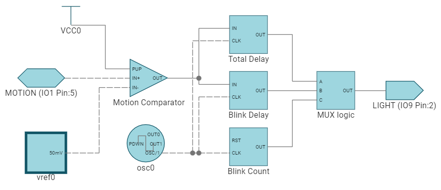
An infrared photodiode placed near the point-of-entry of a room detects the body heat of a person entering the room and outputs a high amount of current as the individual passes by. This current is transformed into a voltage by a transimpedance preamplifier. The analog comparators, included in TPLD1201, allow the device to receive the analog voltage output from the preamplifier. Since each analog comparator has access to either an internal bandgap voltage reference or an external voltage reference from pin IO2, the photodiode detection signal can be compared against a set DC reference voltage without needing an external resistor divider, or against the output of another photodiode elsewhere in the room.
The output of the analog comparator is fed into two parallel delay blocks, which are both triggered to delay only the falling edge of the input signal. One delay block sets the total delay, after the last detected motion from the photodiode, before signalling low to the LED relay to turn off the lighting. The second delay block sets the delay, before the TPLD1201 starts modulating the enable signal to the LED relay, to effectively dim the lights, signaling to anyone still in the room to trigger the sensor again to keep the lights on. The modulation signal is handled by a count block, which sets the rate of modulation, and a LUT, whose input equation is Blink Delay | (Total Delay & Blink Count). The control data of each delay and count block, and the speed of the oscillator used as clock data, can be altered to achieve the desired delays and modulation. The proposed circuit is displayed in Figure 3 and a timing example is given in Figure 4.
 Figure 3 Proposed Occupancy Controlled Lighting
Circuit
 Figure 4 Occupancy Controlled Lighting
Timing
Figure 4 Occupancy Controlled Lighting
TimingMost relays take between 5-20ms to fully switch, so the modulation frequency must be configured so the relay coil is able to switch on and off appropriately, depending on the relay used. The modulation frequency can be calculated by oscillator frequency / count control data. For example, an oscillator with a frequency of 25kHz and a count control data of 100 provides a blinking frequency of roughly 125Hz.
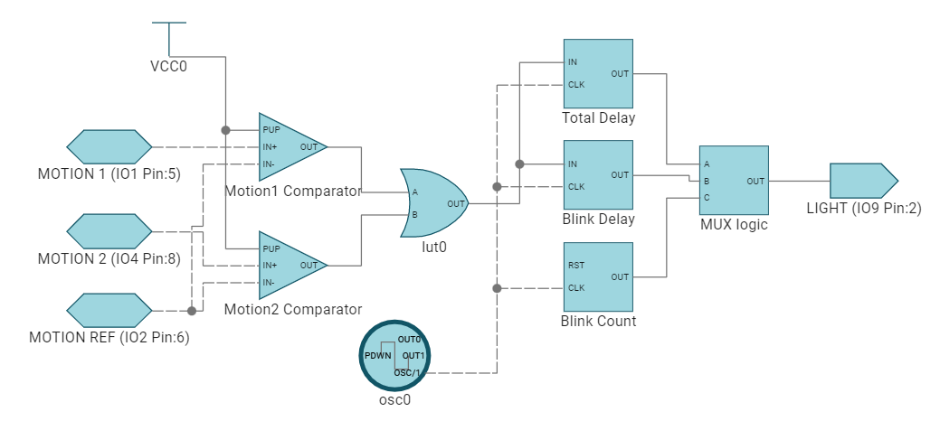
Each analog comparator has the option to be referenced against another external analog signal, or voltage reference, that is fed into pin IO2. In this system, a third photodiode is connected in locations where occupants are not present, or where a more precise voltage reference is present, to allow a more precise infrared light reference voltage. An example of this system is shown in Figure 5. The timing remains the same as in the first circuit, with either motion pin triggering the relay.
 Figure 5 Example Circuit With Two Motion
Detectors and External Reference
Figure 5 Example Circuit With Two Motion
Detectors and External ReferenceConclusion
TPLD1201 removes the need for external analog comparators, or analog-to-digital converters, and acts as an effective replacement for other programmable logic or MCU devices in smart occupancy lighting systems. TPLD1201 is simple to implement, only requiring that the user not exceed the drive strength and capacitive load requirements of the output pins and prevent overvoltage on the input pins. TPLD1201 is an excellent, cost-effective, and size-efficient choice that offers flexibility and versatility to users with more targeted systems that do not require the extra functionality of an FPGA or MCU.
References
For more details on concepts discussed in this article, refer to the following documents:
- Texas Instruments, Basics of Load Switches, application note
- Texas Instruments, Designing Photodiode Amplifier Circuits With OPA128, application bulletin
- Texas Instruments, Photodiode Amplifier Circuit, analog engineer's circuit