SLAA870 February 2019 AFE7422 , AFE7444
-
Evaluating the frequency hopping capability of the AFE74xx
- Trademarks
- 1 Introduction
- 2 Phase Coherency vs Phase Continuity
- 3 AFE74xx Architecture
- 4 Frequency Hopping Methods
- 5 NCO Frequency Resolution Versus Hop Time
- 6 Fast Frequency Hopping With the Load and Switch
- 7 Register Addresses
- 8 References
4.1.1.3 Software Configuration
To conduct the experiment, bring up the AFE74xxEVM in any mode. For this experiment, the AFE74xx EVM is configured to mode 4 (for more information on EVM operating modes, see the RF DAC and ADC Operating Mode Configurations table in the Device Functional Modes section of the respective device data sheet). After the AFE74xx is configured, enable direct digital synthesis (DDS) mode. See Section 3.3.2 to see how to enable DDS mode.
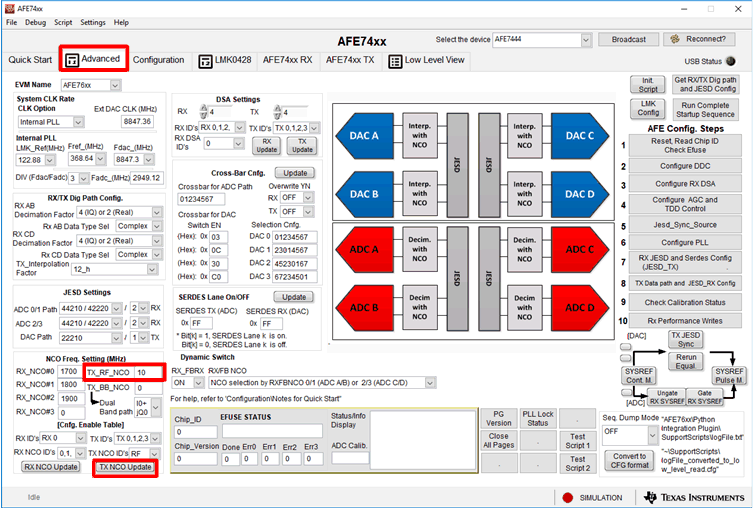
After DDS mode is enabled, the default frequency for TXNCO0 is 1700 MHz, and must be reprogrammed to 10 MHz. Program TXNCO0 to 10 MHz by entering 10 in the RF_TX_NCO field located in the Advanced tab in the AFE74xx GUI. Then press the TX NCO UPDATE button, as shown in Figure 13.
 Figure 13. Programming TXNCO0 to 10 MHz Through the AFE74xx GUI
 At this point, DAC A outputs a constant tone at the location specified by TXNCO0; in this case, 10 MHz. This constant tone is shown on the oscilloscope connected to DAC A SMA output, labeled I_OUTA on the AFE74xxEVM.
The next step is to reprogram TXNCO0 to 100 MHz while capturing the transition on the oscilloscope. In the NCO Settings section of the AFE74xx GUI, change the frequency from 10 MHz to 100 MHz by entering a value of 100 in the TX_RF_NCO field. Before pressing the TX NCO UPDATE button, make sure that the trigger settings on the oscilloscope is set for negative-edge triggering of the SDEN signal. After the trigger is set, navigate back to the Advanced tab in the AFE74xx GUI, make sure that 100 is entered into the TX_RF_NCO field, and press TX NCO UPDATE to reprogram TXNCO0 to 100 MHz. Pressing the TX NCO UPDATE button actively reprograms the frequency in TXNCO0 from 10 MHz to 100 MHz through the GUI using the SPI, and activates the trigger on the oscilloscope to capture the transition.