SLAA871 January   2019 AFE7422 , AFE7444


  1.   AFE74xx as a single-chip wideband repeater using loopback mode
    1.     Trademarks
    2. 1 Introduction
    3. 2 Repeater Mode (RX-TX Loopback With SerDes Bypassed)
      1. 2.1 Overview of the AFE74xx Repeater Mode
      2. 2.2 Configuration of the AFE74xx as a Repeater
      3. 2.3 Programming the Repeater Mode
        1. 2.3.1 Hardware Setup
        2. 2.3.2 Software Setup and GUI Configuration
    4. 3 130-MHz Digital Repeater System Overview
      1. 3.1 Key System Specifications
    5. 4 System Overview
      1. 4.1 Block Diagram
      2. 4.2 Design Considerations
      3. 4.3 Highlighted Products
        1. 4.3.1 LMK04828
      4. 4.4 System Design Theory
    6. 5 Hardware and Testing
      1. 5.1 Measured Latency and Gain
        1. 5.1.1 Hardware
        2. 5.1.2 Test Setup and Results
      2. 5.2 Measured Linearity Performance
        1. 5.2.1 Hardware and Test Setup
        2. 5.2.2 Test Results
      3. 5.3 Measured Selectivity (Out-of-Band Jammer)
        1. 5.3.1 Hardware and Test Setup
        2. 5.3.2 Test Results
    7. 6 Terminology

Test Results

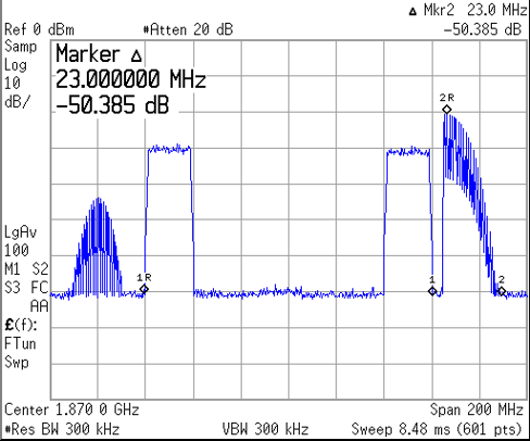
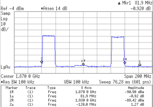
Figure 19 shows a repeated 120-MHz wideband signal at the output of the repeater without the jammer present. Figure 20 shows the jammer swept from the edge of the effective decimation pass band, through the transition band until the jammer is fully attenuated. The resulting measurement shows –50 dBc of attenuation at 23 MHz, as denoted by marker 2.
tida-060007-figure-x-shows-the-repeated-wideband-signal-simulating-a-120mhz-carrier-scope-shot.png
Figure 19. Repeated Wideband Signal Simulating
a 120-MHz Carrier
tida-060007-figure-x-shows-50-dbc-attenuation-at-23mhz-outside-decimation-bandwidth-scope-shot.pngFigure 20. –50-dBc Attenuation at 23-MHz Outside Decimation Bandwidth