SLAA907D September 2019 – December 2021 PGA450-Q1 , PGA460 , PGA460-Q1 , TDC1000 , TDC1000-Q1 , TDC1011 , TDC1011-Q1 , TUSS4440 , TUSS4470
2.2 The Ultrasonic Echo and Signal Processing
TI recommends to drive transducers with a sine or square wave at their center frequency to achieve the best results. Most integrated solutions have an output driver consisting of low-side drivers to drive a transformer in a transformer-drive situation, or FETs in an h-bridge configuration for a direct drive solution.
After the transducer sends out an echo at its resonant frequency, the system must then listen for return echoes which are a result of an object in the transducer's field of view. Ultrasonic systems typically filter the return echo to remove noise and gain the signal up before it goes to an ADC. Some ways to gain the ultrasonic system are as follows:
- Digital Gain / Fixed Gain: apply a fixed gain to the entire ultrasonic echo.
- Time-Varying-Gain: apply a gain that is dependent on how far out an object is. Often, objects that are further out in time produce a weaker echo response and objects that are closer produce a stronger echo response. To combat this, to prevent saturation of the close signals, and to be able to identify the further objects, one may choose to gain their system such that a small gain is applied early in time, and a larger gain is applied further out in time. This gives the user flexibility to configure their gain based on their system requirements.
- Automatic Gain Control / Logarithmic Amplifier: a logarithmic amplifier approach is a way to achieve automatic gain control when dealing with input signals that are both high and low in amplitude. A log amp gains an input signal based on the log scale which helps get a stronger echo response from weak signals while also appropriately gaining the strong signals but preventing saturation, similar to the time-varying-gain approach. Whereas the time-varying-gain method is dependent on where an object is in time, the logarithmic amplifier is dependent on the actual echo of the input signal itself with no dependency on time.
Designers can check the zero-crossing frequency data to verify that the return echo is that of the transducer. This can also be used to detect doppler-shifts, which is the change in frequency of the emitted sound wave, to detect motion and its direction.
Once the return signal has been filtered and gained appropriately, the data can be sent to the ADC for further signal processing. Figure 2-2 shows the signal from the ADC output.
 Figure 2-2 Typical Output From
ADC
Figure 2-2 Typical Output From
ADCAfter the signal is digitized, it is ready to go to a digital signal processor (DSP) or an MCU for further processing. First, it goes through a bandpass filter to reduce any out-of-band noise.
 Figure 2-3 Typical Output From Bandpass
Filter
Figure 2-3 Typical Output From Bandpass
FilterThe next stage is to rectify the signal to extract the absolute value of the signal as shown in Figure 2-4.
 Figure 2-4 Typical Output From
Rectifier
Figure 2-4 Typical Output From
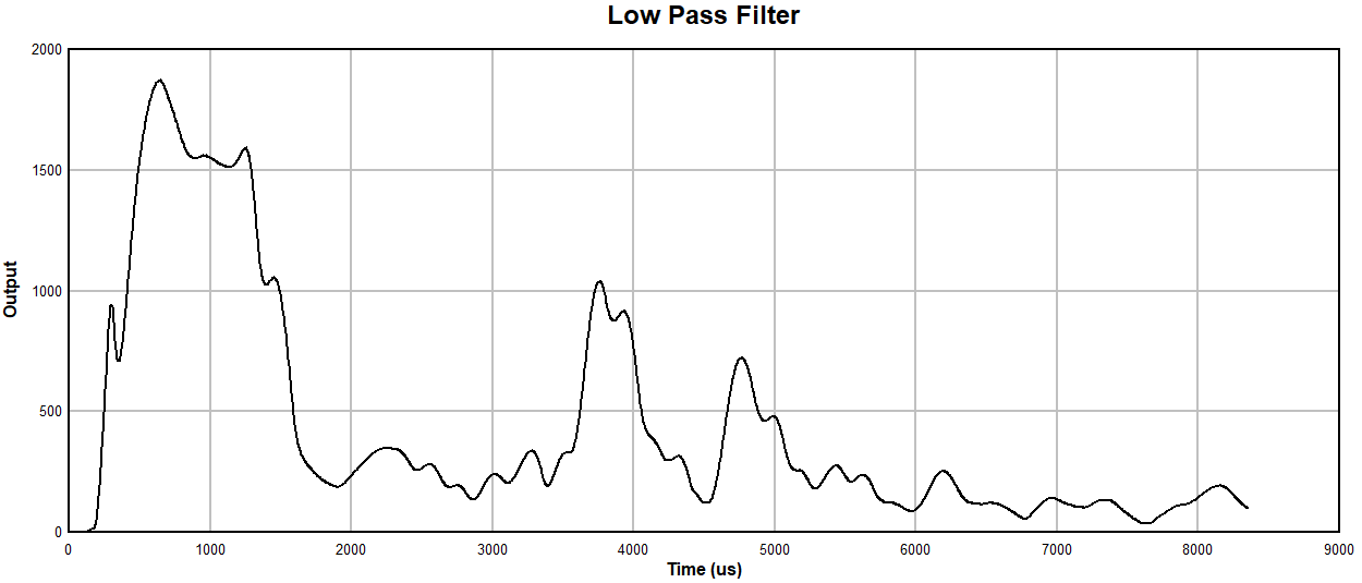
RectifierAfter rectification, there is often a peak hold in place before a low-pass filter is applied to ensure the peak amplitude of the rectified signal is not filtered out. Together with the peak hold and low-pass filter, a demodulated output can be produced as shown in Figure 2-5. This makes it easy to apply thresholds to further customize the signal to eliminate noise and extract time-of-flight data and echo width and amplitude information. The demodulated signal is also referred to as an envelope signal.
 Figure 2-5 Typical Output From Low-Pass
Filter