-
7-Segment LED Stopwatch Made Simple With Low-Cost MSP430 MCU SLAA999 February 2021 MSP430FR2422 , MSP430FR2433
-
7-Segment LED Stopwatch Made Simple With Low-Cost MSP430 MCU
7-Segment LED Stopwatch Made Simple With Low-Cost MSP430 MCU
Application Brief
Segment LED displays provide information to users in a wide variety of applications from simple timers to smart meters and more. This application uses a two-digit, 7-segment LED display to display the time of a stopwatch. The demonstration uses the MSP430FR2433 microcontroller (MCU) to implement the stopwatch and a GUI implementation to additionally toggle individual LEDs and display a user number input.
Implementation
This application uses a two-digit, common-anode 7-segment LED to display the stopwatch time. The MCU measures the time using the Timer_A peripheral and general purpose output pins to drive the LEDs so that it displays the time. There are two buttons to control the time - one is to start and stop the stopwatch, and the other is to clear the timer. The LEDs and the buttons are connected to the MSP430FR2433 using digital I/O pins and current-limiting series resistors. Figure 1-1 shows the stopwatch block diagram.
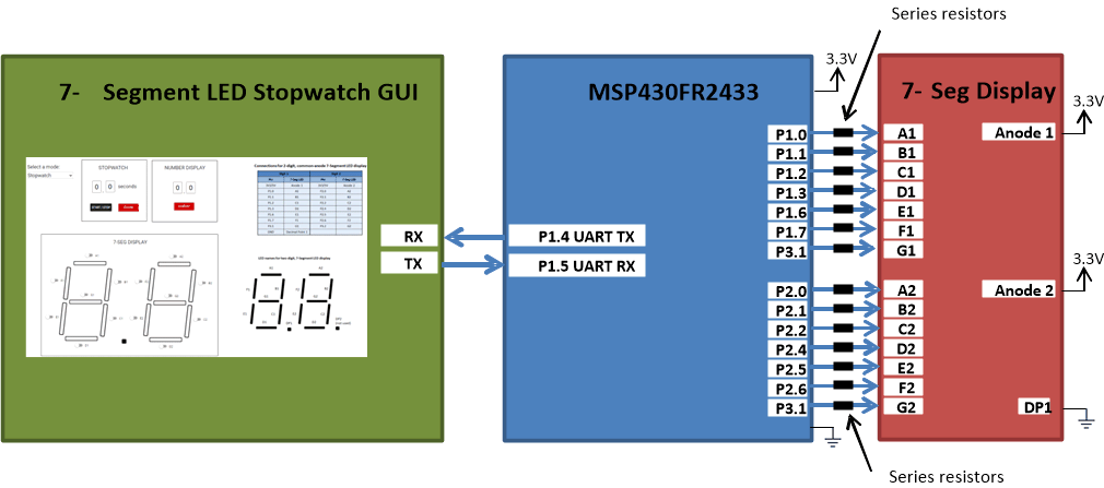 Figure 1-1 Implementation Overview
A seven-segment LED display consists of seven discrete LEDs named A-G and optional decimal points named DP. In this application, we will use a common-anode, 2-digit seven-segment display. Therefore, all of the LEDs in each digit share a common anode pin sourced by 3.3 V or 5 V and light up when the outputs are sunk to ground. Seven-segment displays can reduce the amount the general output pins needed by using a display with multiplexed I/O pins or an I2C, SPI, or UART backpack. A backpack is a small Printed Circuit Board (PCB) that is integrated with or soldered to a display and is used to communicate to it using less pins than I/O pins from the microcontroller. For instance, this example uses 14 I/O pins to use the two-digit 7-segment display whereas a display with an I2C backpack may only require 4 pins (VCC, GND, SDA, and SCK).
Figure 1-2 shows the top view of the 7-segment LED display used in this application.
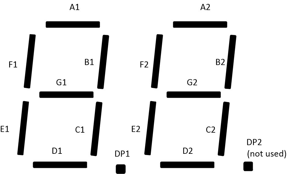 Figure 1-2 2-Digit, Common-Anode 7-Segment LED
Display Top View
Figure 1-2 2-Digit, Common-Anode 7-Segment LED
Display Top ViewThe MSP430FR2433 LaunchPad™ Development Kit (shown in Figure 1-3) is used with this example project, but it can be used for any MSP430™ microcontroller with proper code migration. Backchannel USB-to-UART is used on eZ-FET of the LaunchPad kit is used for UART communication with the GUI, and the receive and transmit pins are tied to P1.4 and P1.5, respectively. The buttons P2.3 and P2.7 are used as inputs to start/stop the timer and clear the time, similar to a standard stopwatch. This leaves 14 available GPIO pins on the MSP430FR2433 LaunchPad. These are used to turn on the 14 segments and display numbers on the two digits of the 7-seg display.
Current-limiting series resistors are recommended for the fourteen 7-segment display connections to reduce the amount of current consumption from the onboard 3.3 V LDO on the LaunchPad. For more information, see the device-specific data sheet specification of the 7-segment LED display used to determine the forward current consumption when the LED turns on.
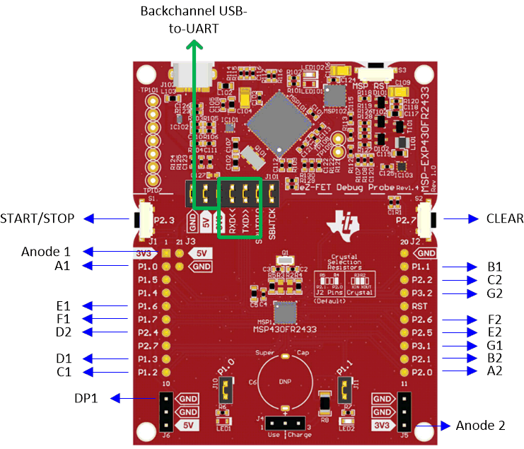 Figure 1-3 MSP430FR2433 LaunchPad and
Connections
Figure 1-3 MSP430FR2433 LaunchPad and
ConnectionsPerformance
The MSP430FR2433 has pre-configured functions to display any number 0-9 to the first or second digit in the standalone software. Because the main functionality is implementing a stopwatch timer to count from 0.0 to 9.9 seconds, decimal point 1 (DP1) is always ON and decimal point 2 (DP2) is unused. Therefore, DP1 is connected to ground to keep it illuminated.
The buttons P2.3 and P2.7 are initialized as inputs with interrupts to detect a button press. P2.3 is used to start or stop the stopwatch, and P2.7 resets the time to 0.0 seconds. When the start button is pressed, the main function enters a simple state machine to go from the RESET state to the START state. Once in the START state, the timer counts to 9.9 seconds. When the stop button is pressed, the code goes from the START to the STOP state, and the timer can be started again from the current time or reset back to 0.0 seconds.
Timer_A0 is initialized to interrupt every 0.1 seconds. When a Timer_A0 interrupt occurs, the current time is incremented and outputted to the 7-segment display using the pre-configured display functions. When the code is not in the Timer_A0 interrupt, the MSP430FR2433 remains in a low-power mode.
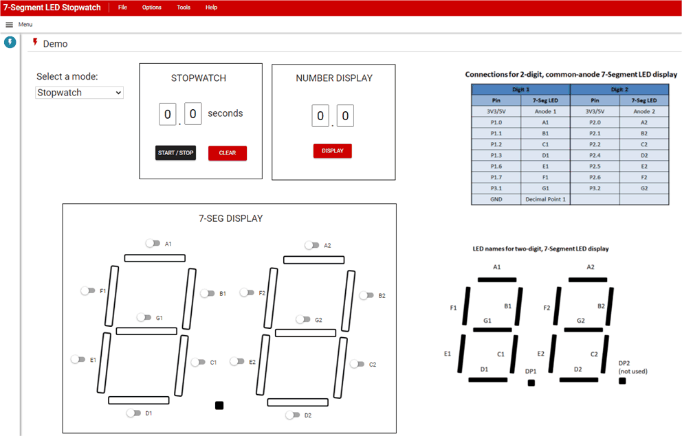 Figure 1-4 7-Segment LED Stopwatch GUI
The 7-Segment LED Stopwatch GUI shown in Figure 1-4 includes a drop-down menu to select whether the user wants to use the 7-segment display as a Stopwatch, Number Display, or LED Toggle. The stopwatch performs the same functionality as the standalone code example, but the Start/Stop and Clear buttons can be used instead of P2.3 and P2.7. Number display allows the user to enter two numbers and output those numbers to the first and second digits of the display. The LED toggle mode lets the user individually toggle each LED segment by clicking on the button next to it.
A summary of the software flowchart and GUI flow is shown in Figure 1-5.
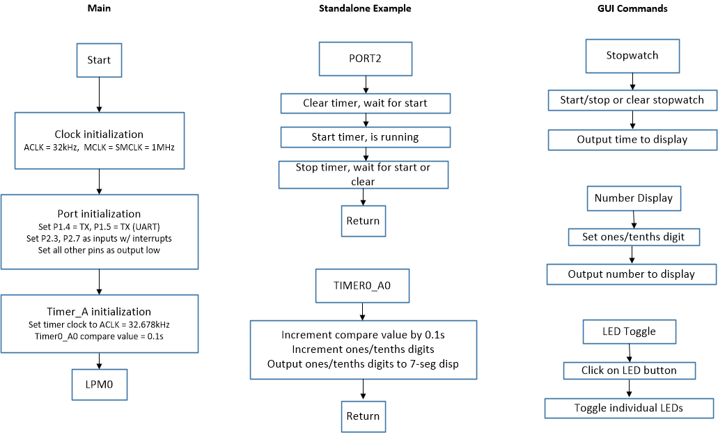 Figure 1-5 Software Flowchart
To Get Started
- Watch our training video “7-Segment LED Stopwatch”, where we walk through how to use the MSP430FR2433 as a low-power stopwatch using a 7-Segment LED Display.
- Order an MSP430FR2433 LaunchPad kit to evaluate the 7-Segment LED Stopwatch example Code.
- Download and test this example with the 7-Segment LED Stopwatch example GUI, where you can use the MCU as a stopwatch, output numbers to the display, or toggle individual LED segments.
- Evaluate the 7-Segment LED Stopwatch example code for the MSP430FR2433 LaunchPad kit.
Device Recommendations
| Part Number | Key Features |
|---|---|
| MSP430FR2433 | 16KB FRAM, 4KB SRAM, 10-bit ADC, UART/SPI/I2C, Timer |
| MSP430FR2422 | 8KB FRAM, 2KB SRAM, 10-bit ADC, UART/SPI/I2C, Timer |