SLAAE76B march 2023 – june 2023 MSPM0G1105 , MSPM0G1106 , MSPM0G1107 , MSPM0G1505 , MSPM0G1506 , MSPM0G1507 , MSPM0G3105 , MSPM0G3106 , MSPM0G3107 , MSPM0G3505 , MSPM0G3506 , MSPM0G3507
4.1 Internal Oscillators
Internal Low-Frequency Oscillator (LFOSC)
LFOSC is an on-chip low power oscillator that is factory trimmed to a frequency of 32.768 kHz. It provides a low-frequency clock that can be used to help the system achieve low power consumption. The LFOSC can provide higher accuracy when used over a reduced temperature range. See the device-specific data sheet for details.
 Figure 4-1 MSPM0G Series LFOSC
Internal System Oscillator (SYSOSC)
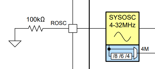
SYSOSC is an on-chip, accurate, and configurable oscillator with factory-trimmed frequencies of 32 MHz (base frequency) and 4 MHz (low frequency), as well as support for user-trimmed operation at either 24 MHz or 16 MHz. It provides a high frequency clock that allows the CPU to run at high speed for executing code and processing performance.
 Figure 4-2 MSPM0G Series SYSOSC
SYSOSC Frequency Correction Loop
The additional hardware setting for this oscillator is an external resistor, populated between the ROSC pin and VSS, to increase SYSOSC from a base accuracy of ±2.5% across temperature.
The overall SYSOSC application accuracy is determined by combining the following error sources to determine the total error:
- The ROSC reference resistor error (due to tolerance and temperature drift)
- The SYSOSC circuit error in FCL mode (±0.75% for -40°C to 85°C or ±0.90% for -40°C to 125°C)
Table 4-1 shows how to calculate the SYSOSC application accuracy for two different ROSC resistor specs across two temperature ranges. For more details, see the device-specific TRM.
| Ambient Temperature (TA) | -40 ≤ TA ≤ 125°C | -40 ≤ TA ≤ 85°C | ||
|---|---|---|---|---|
| ROSC Resistor Parameters | ±0.1% 25 ppm/°C | ±0.5% 25 ppm/°C | ±0.1% 25 ppm/°C | ±0.5% 25 ppm/°C |
| Nominal ROSC resistance (ROSCnom) | 100 kΩ | |||
| Maximum ROSC resistance (at 25°C) | 100.1 kΩ | 100.5 kΩ | 100.1 kΩ | 100.5 kΩ |
| Minimum ROSC resistance (at 25°C) | 99.9 kΩ | 99.5 kΩ | 99.9 kΩ | 99.5 kΩ |
| ROSC resistor TCR | 25 ppm/°C | |||
| ROSC temperature drift | -0.16% to 0.25% | -0.16% to 0.15% | ||
| Maximum ROSC resistance (at high temperature) (ROSCmax) | 100.35 kΩ | 100.75 kΩ | 100.25 kΩ | 100.65 kΩ |
| Minimum ROSC resistance (at low temperature) (ROSCmin) | 99.74 kΩ | 99.34 kΩ | 99.74 kΩ | 99.34 kΩ |
| ROSC resistance error (high temperature) (ROSCerr+) | +0.35% | +0.75% | + 0.25% | +0.65% |
| ROSC resistance error (low temperature) (ROSCerr-) | -0.26% | -0.66% | -0.26% | -0.66% |
| SYSOSC circuit error (SYSOSCerr) | ±0.9% | ±0.75% | ||
| Total accuracy (TOTerr-, TOTerr+) | -1.2% to +1.3% | -1.6% to +1.7% | -1.0% to +1.0% | -1.4% to +1.4% |
System Phase-Locked Loop (SYSPLL)
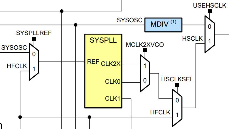
SYSPLL is the system phase-locked loop with programmable frequency and is used to achieve the MSPM0G series highest speed (80 MHz).
 Figure 4-3 MSPM0G SYSPLL Circuit