SLAAEB3A May 2023 – July 2024 MSPM0G3507 , MSPM0L1106 , MSPM0L1306
PRODUCTION DATA
3.1 System Initialization
The sample code described in this application note is created by using MSPM0 I2C interface to control BQ76952 and realize necessary commands. The final code is composed of three types of functions: MSPM0 initializing functions, I2C communication functions and BQ76952 functions. The code shows a demonstration of how to communicate MSPM0 with BQ756952 by I2C interface and implement specific command.
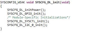
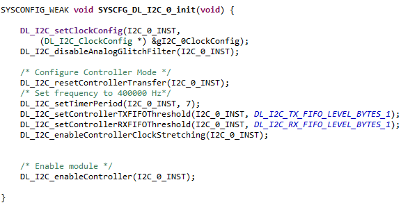
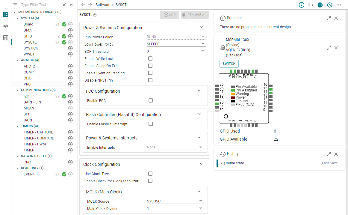
The MSPM0 initialization is for system initialization of MCU power, system controller, system clock, and I2C peripherals, shown in Figure 3-2 and Figure 3-3. All the configuration is done by Sysconfig (Graphic code generation tool). The I2C peripheral in MSPM0 is configured as a Controller device to communicate with BQ769x2.
 Figure 3-2 SYSCFG_DL_init ()
Function
 Figure 3-3 SYSCFG_DL_I2C_0_init ()
Function
Figure 3-3 SYSCFG_DL_I2C_0_init ()
FunctionThe I2C module is initialized by the SYSCFG_DL_I2C_0_init() function. The clock source for I2C module is BUSCLK which depends on the power domain of MSPM0L. The I2C standard bus speed can be configured to Standard Mode(100k), Fast Mode(400k) and Fast Mode Plus(1M), three modes. This code is set to 100kHz. All details of these settings can be found in CCS Sysconfig page.
 Figure 3-4 Sysconfig Setting
Interface