SLAAEE3A July 2023 – June 2024 MSPM0L1306
4.4.2 Flash Data Input Mode
This mode means the battery running data (Vcell, Icell, Tcell) is saved into MCU. This method can remove the need of hardware and increase algorithm running frequency. As you do not need the UART communication, the running frequency is the fastest.
 Figure 4-8 Flash Data Input Mode
Structure
Figure 4-8 Flash Data Input Mode
StructureTo realize this method, you need to use the “Flash saved battery runfile generation” function to convert the SMData file or McuData file into C code.
 Figure 4-9 Battery Runfile
Generation
Figure 4-9 Battery Runfile
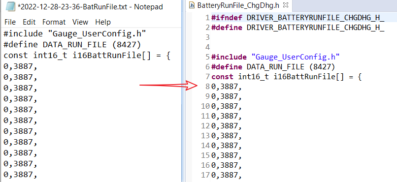
GenerationCopy the code from txt to the C file. After changing the definition of detection mode, run the algorithm with a single launchpad.
 Figure 4-10 Battery Runfile Copy
Remember, as the MCU memory size has limitations, the battery run file input into the MCU cannot be unbounded. If you want to run a long battery cycle test case, you need to change the time step in python code and C code. Reducing the u8AvgVcellDetectPeriod at the same time, if needed.
 Figure 4-11 Code Change for Changing Time
Step