SLAAEE6 October 2023 MSPM0L1306 , MSPM0L1306
1 Introduction
The features of this solution are shown below:
- It supports bi-directional current detection.
- It can self-calibrate the voltage offset and GAIN setting of the OPA.
- It can do dynamic GAIN setting to reach high accuracy across low to high current.
- The detection error at room temperature can reach to ±0.25% at ±2A load.
- The current consumption can reach 8 μA with 1Hz sample rate.
As this solution is mostly developed for MSPM0 Gauge solution, the following section describes how to detect and test the discharge and charge current of a battery. For other current detection use cases, you can also take this note as a reference.
The solution is combined of three parts. All the software and hardware are reused by MSPM0 Gauge solution. You can find all of them at MSPM0 Current Detection Development package. You can also find the MCU code under the SDK (mspm0_sdk_xxx\examples\nortos\LP_MSPM0L1306\battery_gauge).
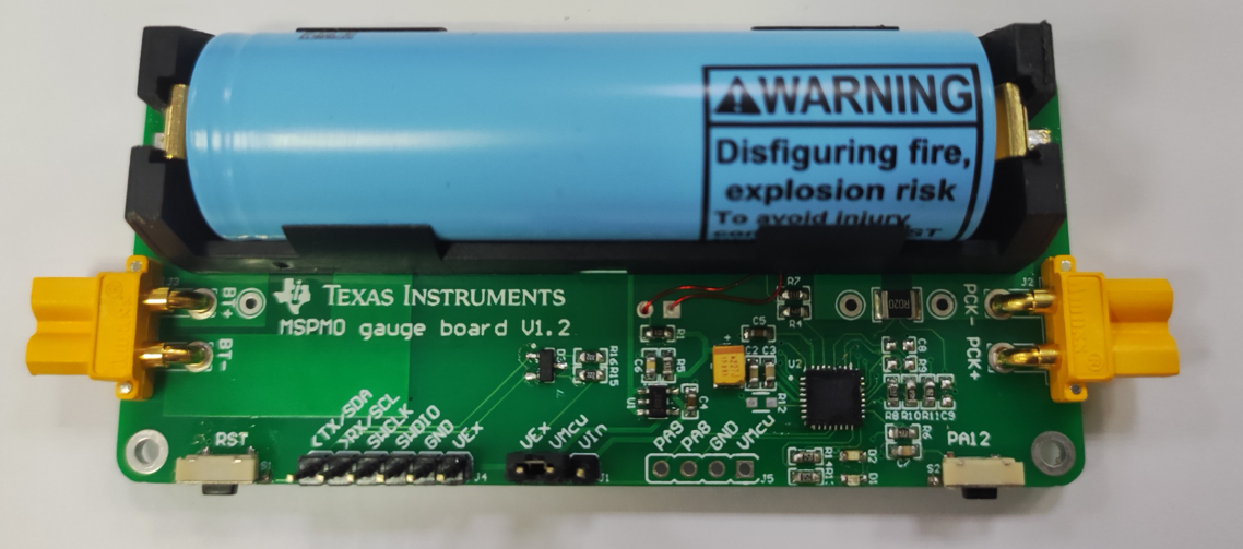
- It is the hardware board that is used to evaluate the current detection solution with
MSPM0L130x integrated.
 Figure 1-1 MSPM0 Current Detection Hardware
Board
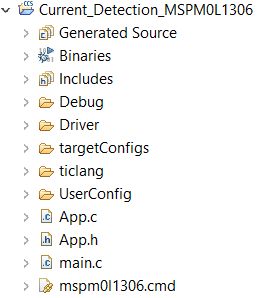
 - It is the software project based on MSPM0L130x.
 Figure 1-2 MSPM0 Current Detection Software
Project
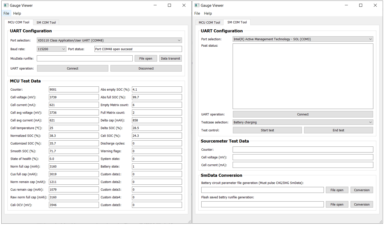
 - It is the GUI. It is written by python, which is mostly used to read the test data from
the board.
 Figure 1-3 MSPM0 Gauge GUI Project