SLAAEE6 October   2023 MSPM0L1306 , MSPM0L1306


  1.   1
  2.   Abstract
  3.   Trademarks
  4. 1Introduction
  5. 2Hardware Introduction
  6. 3Software Introduction
  7. 4Gauge GUI Introduction
  8. 5Current Detection and Calibration Method
    1. 5.1 MSPM0 OPA Introduction
      1. 5.1.1 OPA input and output limitation
      2. 5.1.2 OPA Accuracy Influence
    2. 5.2 Current Detection Method
    3. 5.3 Current Calibration Method
      1. 5.3.1 (R1+R2)/R2 calibration
      2. 5.3.2 OPA1 Voffset calibration
      3. 5.3.3 R3/(R4+R3) calibration
      4. 5.3.4 Vref calibration
  9. 6Solution Evaluation Steps
    1. 6.1 Step1: Hardware Preparation
    2. 6.2 Step2: Evaluation
  10. 7MSPM0 Gauge Solution Test Results
    1. 7.1 Calibration Test Result
    2. 7.2 Current Detection Result
      1. 7.2.1 Test Under 25°C
      2. 7.2.2 Test Under 0°C
      3. 7.2.3 Test Under 50°C
      4. 7.2.4 Conclusion
    3. 7.3 Current Consumption Test
  11. 8Solution Summery and Improvement Direction
    1. 8.1 Shunter Resistor
    2. 8.2 ADC and its Reference
    3. 8.3 Runtime Calibration

OPA input and output limitation

OPA has some parameters related to operation limitations. If above the parameters, the linearity of OPA will get worst. That means the detection current is limited to a certain range.

The key parameters are common-mode voltage range and voltage output swing. Figure 5-2 shows the limitation value of MSPM0L130x, when set VDD as 1.8 V and RRI=1. For this device, to reach the typical open-loop voltage gain value on data sheet, output voltage should be controlled into a smaller voltage range (0.3 V ~ VDD-0.3 V) , compared with voltage output swing range. If above the range, the open-loop gain will be decreased. In this current detection demo, it doesn’t take the open-loop gain into consideration which has smaller influence than other two parameters, especially under low gain setting.
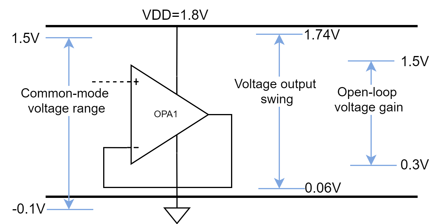
GUID-FE2F707D-F24F-45B5-8DDE-DDE3DCD3015A-low.pngFigure 5-2 MSPM0 OPA Limitation