SLAAEF6 September   2023 MSPM0L1105 , MSPM0L1106 , MSPM0L1306 , MSPM0L1344 , MSPM0L1345 , MSPM0L1346


  1.   1
  2.   Abstract
  3.   Trademarks
  4. 1PIR Design Description
    1. 1.1 PIR Sensor
    2. 1.2 PIR Signal Chain
      1. 1.2.1 Traditional Motion Detection Signal Chain Design
      2. 1.2.2 Capacitor-Free Signal Chain Design
  5. 2Hardware and Schematic
    1. 2.1 MSPM0L1306
    2. 2.2 MSPM0 PIR Boosterpack
      1. 2.2.1 Schematic
  6. 3Software
    1. 3.1 Software Architecture
    2. 3.2 Software Flow Chart
    3. 3.3 Data Processing
      1. 3.3.1 Digital Signal Conditioning
      2. 3.3.2 Low-Pass Filter for Temperature Drift
      3. 3.3.3 Spikes and Noise
      4. 3.3.4 Motion Detection Function
  7. 4Results
    1. 4.1 Power Profile and Current Consumption
    2. 4.2 Detection Performance
      1. 4.2.1 Distance: 5 meters (16.4 ft)
      2. 4.2.2 Distance: 9 meters (29.5 ft)
      3. 4.2.3 Distance: 10 meters (32.8 ft)
  8. 5Summary
  9. 6References

Capacitor-Free Signal Chain Design

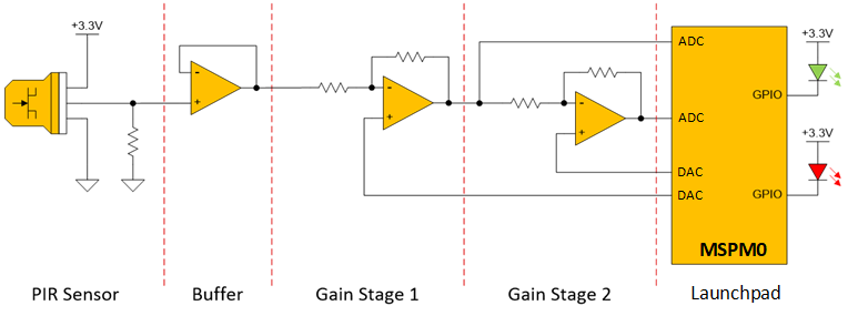
Figure 1-6 shows a simplified version of our capacitor-less signal chain. The signal chain now is mostly purely buffering and gain stages. To remove DC blocking capacitors in the traditional circuit that were adding noise to the system, the stages are being biased using DACs. Instead of using comparators, the signals are fed into an analog-to-digital converter (ADC) which enables a feedback loop for the DAC for tracking changes to environment and ambient temperature and allows digital filtering of the signal.
GUID-D9FD7FBD-38C0-4A57-8F7A-34F037442DA8-low.pngFigure 1-6 Capacitor Free Signal-Chain

The biggest benefit of the MSPM0 solution is that this entire signal chain is integrated into the MCU and is software configurable. The MSPM0L1306 is the most cost effective solution and it includes two operational amplifiers (OPAs). Each of these OPA's are zero-drift, zero-crossover chopper opamps with configurable gain from 1-32x. The MSPM0L1306 also includes one 8-bit reference DAC which is used to bias one stage for the signal chain. For the second stage, a PWM DAC was created using the general purpose amp (GPAMP) and a timer output channel.Figure 1-7 illustrates the improved interface to the PIR sensor leveraging the full signal chain inside the MSPM0L1306. The OPAs can be chained together inside the chip, connected directly to the ADC, and can be shutdown/power-cycled for lowest possible sleep currents.
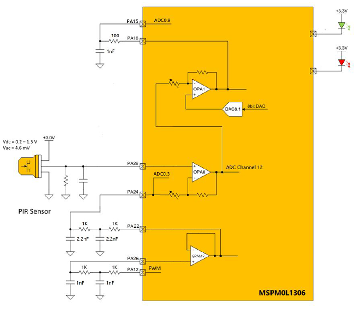
GUID-39EECEB5-D286-4EAE-8465-E99DFF2C1AB3-low.pngFigure 1-7 PIR Signal-Chain Integrated into MSPM0L1306