SLAAEF9 November   2023 MSPM0L1306


  1.   1
  2.   Abstract
  3.   Trademarks
  4. 1MSPM0 Portfolio Overview
    1. 1.1 Introduction
    2. 1.2 Portfolio Comparison of Renesas RL78 MCUs to MSPM0 MCUs
  5. 2Ecosystem And Migration
    1. 2.1 Ecosystem Comparison
      1. 2.1.1 MSPM0 Software Development Kit (MSPM0 SDK)
      2. 2.1.2 The IDE Supported By MSPM0
      3. 2.1.3 SysConfig
      4. 2.1.4 Debug Tools
      5. 2.1.5 LaunchPad
    2. 2.2 Migration Process
      1. 2.2.1 Step 1. Choose The Right MSPM0 MCU
      2. 2.2.2 Step 2. Set Up IDE And Quick Introduction of CCS
        1. 2.2.2.1 Set Up IDE
        2. 2.2.2.2 Quick Introduction of CCS
      3. 2.2.3 Step 3. Set Up MSPM0 SDK And Quick Introduction of MSPM0 SDK
        1. 2.2.3.1 Set Up MSPM0 SDK
        2. 2.2.3.2 Quick Introduction of SDK
      4. 2.2.4 Step 4. Software Evaluation
      5. 2.2.5 Step 5. PCB Board Design
      6. 2.2.6 Step 6. Mass Production
    3. 2.3 Example
  6. 3Core Architecture Comparison
    1. 3.1 CPU
    2. 3.2 Embedded Memory Comparison
      1. 3.2.1 Flash Features
      2. 3.2.2 Flash Organization
        1. 3.2.2.1 Flash Memory Regions
        2. 3.2.2.2 NONMAIN Memory of MSPM0
        3. 3.2.2.3 Flash Memory Registers of RL78
      3. 3.2.3 Embedded SRAM
    3. 3.3 Power UP and Reset Summary and Comparison
    4. 3.4 Clocks Summary and Comparison
      1. 3.4.1 Oscillators
        1. 3.4.1.1 MSPM0 Oscillators
      2. 3.4.2 Clock Signal Comparison
    5. 3.5 MSPM0 Operating Modes Summary and Comparison
      1. 3.5.1 Operating Modes Comparison
      2. 3.5.2 MSPM0 Capabilities in Lower Modes
      3. 3.5.3 Entering Lower-Power Modes
      4. 3.5.4 Low-Power Mode Code Examples
    6. 3.6 Interrupts and Events Comparison
      1. 3.6.1 Interrupts and Exceptions
        1. 3.6.1.1 Interrupt Management of RL78
        2. 3.6.1.2 Interrupt Management of MSPM0
      2. 3.6.2 Event Handler of MSPM0
      3. 3.6.3 Event Link Controller (ELC) of RL78
      4. 3.6.4 Event Management Comparison
    7. 3.7 Debug and Programming Comparison
      1. 3.7.1 Debug Comparison
      2. 3.7.2 Programming Mode Comparison
        1. 3.7.2.1 Bootstrap Loader (BSL) Programming of MSPM0
        2. 3.7.2.2 Serial Programming (Using External Device) of RL78
  7. 4Digital Peripheral Comparison
    1. 4.1 General-Purpose I/O (GPIO, IOMUX)
    2. 4.2 Universal Asynchronous Receiver-Transmitter (UART)
    3. 4.3 Serial Peripheral Interface (SPI)
    4. 4.4 Inter-Integrated Circuit (I2C)
    5. 4.5 Timers (TIMGx, TIMAx)
    6. 4.6 Windowed Watchdog Timer (WWDT)
    7. 4.7 Real-Time Clock (RTC)
  8. 5Analog Peripheral Comparison
    1. 5.1 Analog-to-Digital Converter (ADC)
    2. 5.2 Comparator (COMP)
    3. 5.3 Digital-to-Analog Converter (DAC)
    4. 5.4 Operational Amplifier (OPA)
    5. 5.5 Voltage References (VREF)

Quick Introduction of SDK

When you have finished downloading, the file content is shown in the SDK folder, which is "c:/ti/mspm0_sdk_xxx" by default, as shown in Figure 2-28, among which the mostly used folders are examples folder and docs folder.
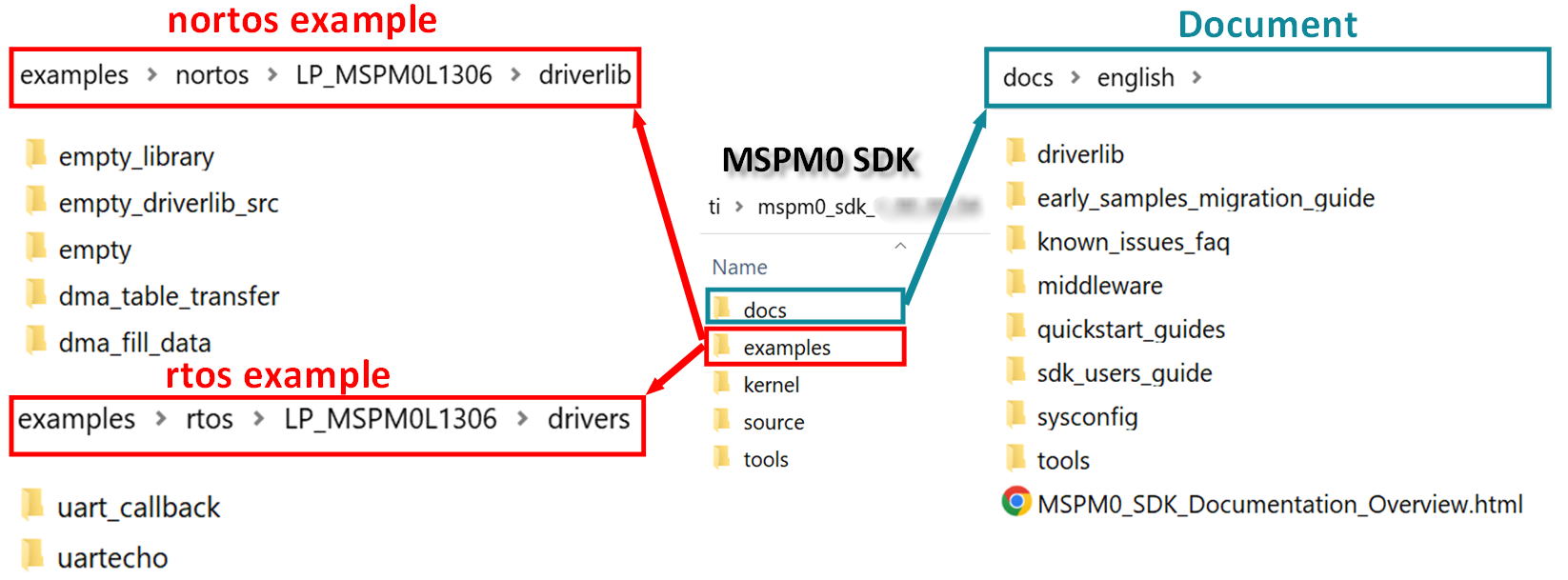
GUID-95008B05-02FB-4032-902D-0141A14E31C1-low.png Figure 2-28 MSPM0 SDK Fold

Table 2-6 shows a summary of example coverage.

Table 2-6 MSPM0 Example Coverage
Supported by SDK Platform
IDE CCS Keil IAR
Compilers TI Arm-Clang GUN Arm Arm/Keil Compiler IAR Arm compiler
RTOS FreeRTOS
Code examples Driverlib/TI Dirvers(drivers)

In nortos examples, you can also find three empty projects for users to build their own project. Table 2-7 the differences.

Table 2-7 Empty Project Description
Example Use Sysconfig Include Library Files Into Project
empty Yes No
empty_library No Yes
empty_driverlib_src (Suggested) Yes Yes

As for docs folder, the structure and the important documents are shown in Figure 2-29.
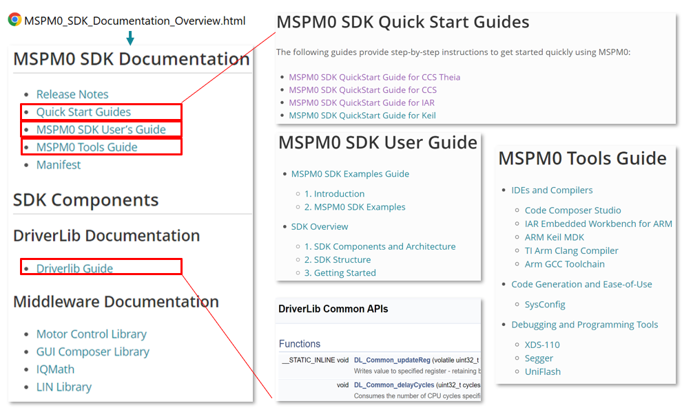
GUID-DD328815-0027-4DC7-9353-2B95C7185670-low.png Figure 2-29 Document Overview