SLAAEK6 June 2024 ULC1001 , ULC1001-Q1
3.2 LCS Architecture
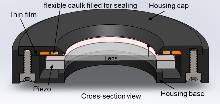
A good architecture is highly reliable, low power, simple to assemble, and low cost. There can be different LCS architectures that can achieve the goal of cleaning water, and one of them is shown in Figure 3-2. A few key points for the architecture can be summarized as:
- The piezo transducer is concentric and directly coupled to the flat circular lens with glue. The glue must be very strong and own a high modulus so the vibration can be transmitted from the piezo to the lens with high efficiency.
- An annular-shaped film is used to attach the lens with the piezo transducer to the housing. The inner side of the film is bonded or glued to the top of the lens and the outer side is bonded or glued to the housing. The thin film has little impact on the resonant frequencies and mode shape of the piezo transducer and lens subsystem.
- The watertight seal is formed by filling in the flexible glue or caulk in the housing cap trench.
- Piezo is floating, with a small distance from the housing base landing spot, which can help prevent damage to the membrane from large loading on the lens.
- Housing cap and housing base are connected through screws, sandwiching the thin film. Bonding or gluing the cap to base directly without using the screws can be also an option.
 Figure 3-2 The Cross-Section View of the
LCS
Figure 3-2 The Cross-Section View of the
LCSNote:
Improper boundary conditions for the lens cover can induce significant damping to the whole system. The flexible thin film and seal are chosen as the interface between the Lens Cover and Housing to keep a low damping level in the design.