SLAAEK6 June 2024 ULC1001 , ULC1001-Q1
2 Introduction
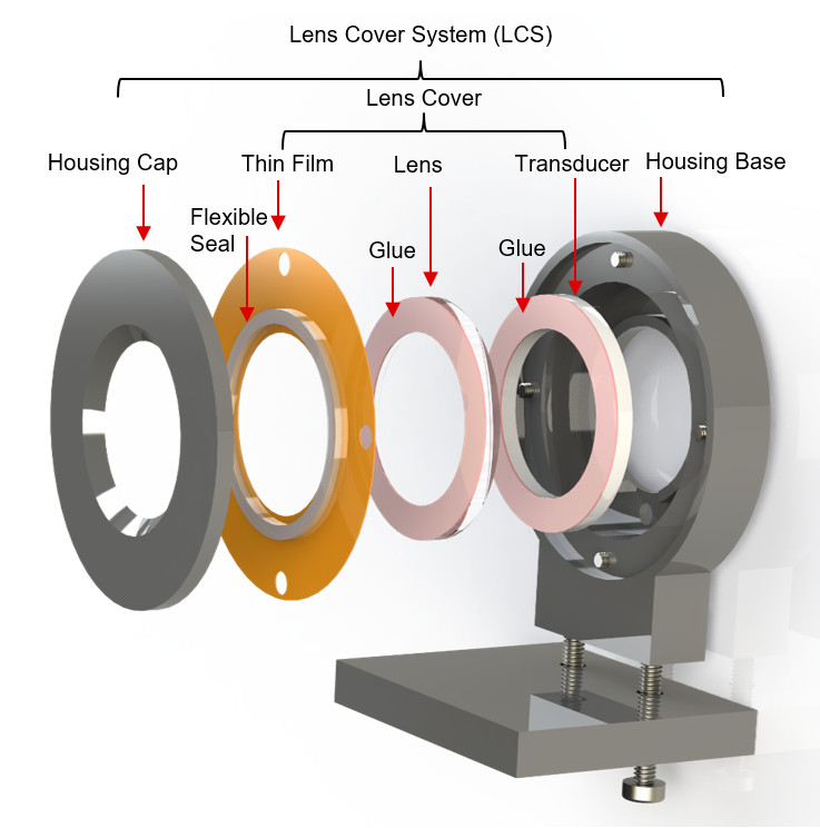
The Ultrasonic Lens Cleaning (ULC) system is an electro-mechanical design to automatically detect and clean water, ice, or other contaminants from cover lenses in automotive, security, and industrial camera systems. The mechanical portion of the technology is called the Lens Cover System (LCS). Figure 2-1 illustrates the components of the ring piezo based LCS, which consists of a housing cap, flexible seal, thin film, lens, glue, ring transducer, and housing base. A transducer glued to the lens and the thin film makes up the Lens Cover. The Lens Cover is mounted inside a housing (cap + seal+ base) to create the LCS.
 Figure 2-1 Illustration of Flat Lens Cover System (LCS)
The lens mentioned in the document is a component of the LCS system and covers the camera lens and is not part of the conventional camera lens system.