SLAAEL9 October 2024 MSPM0C1104 , MSPM0L1306
5.2 Protocol Introduction
This section presents the support command for this demonstration. The gpioDirectionSet function is used to enable or disable GPIO output. Because MSPM0 can enable GPIO input and output at the same time, GPIO input is always enabled. Then every bit in the direction byte is used to enable or disable GPIO output. A 1 means enabling GPIO output and input, and a 0 means only enabling GPIO input. See Table 4-1 for the relationship between the controlled bit and GPIO.
| Type | Header | Command | Direction | Checksum |
|---|---|---|---|---|
| gpioDirectionSet | 0x5A | 0x01 | 1 Byte (1: OUT; 0: IN) | 1 Byte |
The gpioOutputCtl function is used to control GPIO output. Then every bit in the output control byte is used to set GPIO output high or output low. A 1 means outputting high, and a 0 means outputting low. Remember this function only works after the primary send gpioDirectionSet function. See Table 4-1 for the relationship between the controlled bit and GPIO.
| Type | Header | Command | Output Control | Checksum |
|---|---|---|---|---|
| gpioOutputCtl | 0x5A | 0x02 | 1 Byte(1: High; 0: Low) | 1 Byte |
The gpioStateRead function is used to read the GPIO status. The primary needs to send this command to the secondary, and then the secondary sends the GPIO state back to the primary. Then every bit in the pin state byte sent by the secondary is used to show the GPIO state. A 1 means the GPIO state is high, and a 0 means the GPIO state is low. This command can also be used to check whether the GPIO control is as expected, after the primary sends the gpioOutputCtl command. See Table 4-1 for the relationship between the controlled bit and GPIO.
| Type | Header | Command | Pin State | Checksum |
|---|---|---|---|---|
| gpioStateRead | 0x5A | 0x03 | 1 Byte(1: High; 0: Low) | 1 Byte |
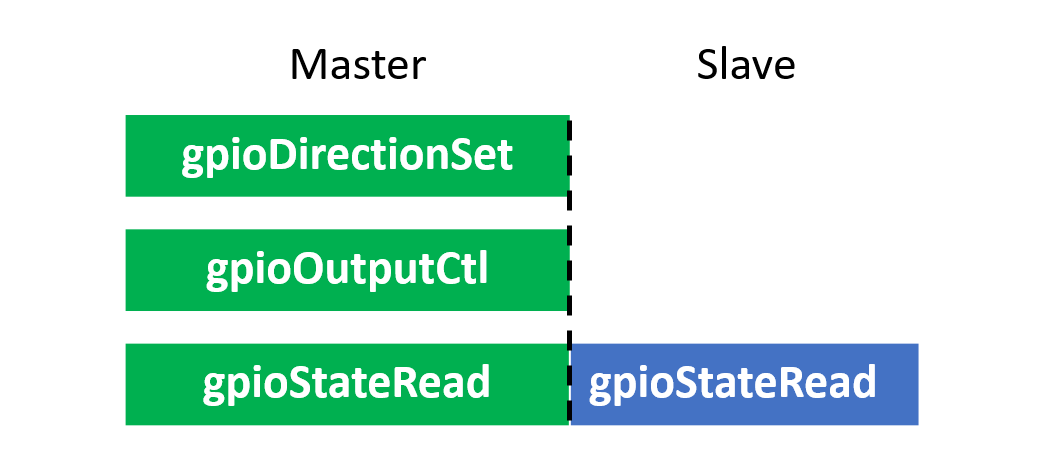
Figure 5-4 shows the command send conditions on the primary and secondary, see also Section 7.
 Figure 5-4 Command Send
Conditions