SLAAEL9 October 2024 MSPM0C1104 , MSPM0L1306
5.1 Code Introduction
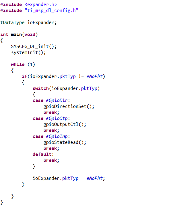
Figure 5-2 shows the main function code in this design. The main function initializes the system configuration and then enters a loop to handle IO control. The code supports three functions for IO control: gpioDirectionSet, gpioOutputCtl, and gpioStateRead. See also Protocol Introduction.
 Figure 5-2 Main Function
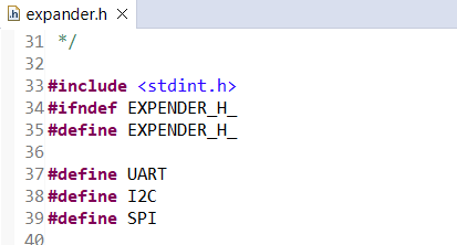
UART, I2C, and SPI are enabled by default. Uncomment the definition in the expander.h file for real implementation, as Figure 5-3 shows.
 Figure 5-3 Communication Enable and
Disable
Figure 5-3 Communication Enable and
DisableAll the communication command reception is done in the relative interrupts. Using UART, command transmission is done in the gpioStateRead() function. Command transmission is done in the relative interrupts for SPI and I2C.