SLAAEO8 October 2024 MSPM0C1103 , MSPM0C1103-Q1 , MSPM0C1104 , MSPM0C1104-Q1 , MSPM0G1105 , MSPM0G1106 , MSPM0G1107 , MSPM0G1505 , MSPM0G1506 , MSPM0G1507 , MSPM0G1519 , MSPM0G3105 , MSPM0G3105-Q1 , MSPM0G3106 , MSPM0G3106-Q1 , MSPM0G3107 , MSPM0G3107-Q1 , MSPM0G3505 , MSPM0G3505-Q1 , MSPM0G3506 , MSPM0G3506-Q1 , MSPM0G3507 , MSPM0G3507-Q1 , MSPM0G3519 , MSPM0L1105
1.1 SAR ADC Principle
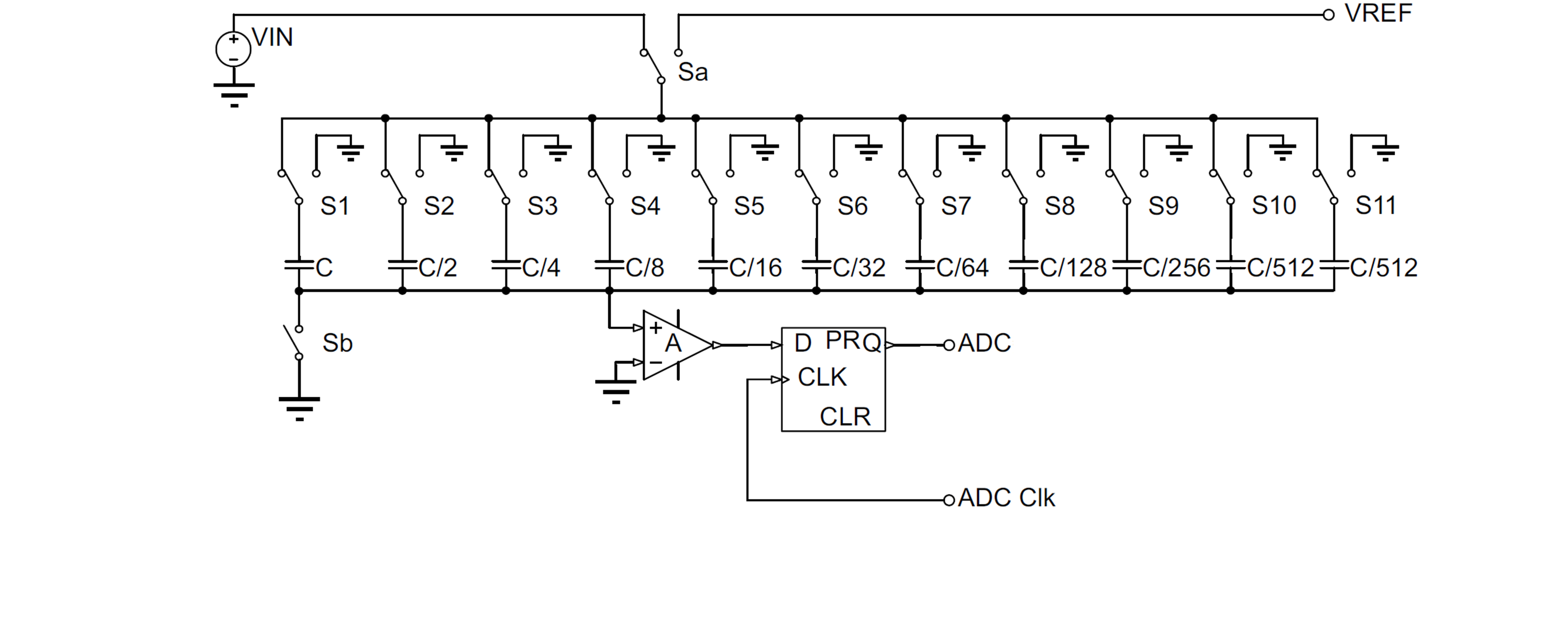
Figure 1-1 shows the system schematic diagram of SAR ADC. SAR ADC controls the switching of multiple switches (12 switches in this case) to perform capacitive voltage division on VREF and obtain different analog voltage output results. Compare the analog voltage with the input sampling signal, and the output of the comparator is used to adjust the on/off state of the switch, ultimately making the simulated voltage obtained by VREF voltage division as close as possible to the input voltage. The actual comparison process is achieved by using the binary method to approximate VREF division for the VIN, thus requiring 12 cycles for data conversion. When considering the ADC triggering, signal sampling and holding time, the actual SAR ADC conversion process takes more than 12 cycles (It takes 14 conversion cycles in MSPM0 G-Series).

Figure 1-1 Principle Block Diagram of SAR ADC Based on CDAC