SLAAEO9 October 2024 MSPM0C1103 , MSPM0C1103-Q1 , MSPM0C1104 , MSPM0C1104-Q1 , MSPM0G1105 , MSPM0G1106 , MSPM0G1107 , MSPM0G1505 , MSPM0G1506 , MSPM0G1507 , MSPM0G1519 , MSPM0G3105 , MSPM0G3105-Q1 , MSPM0G3106 , MSPM0G3106-Q1 , MSPM0G3107 , MSPM0G3107-Q1 , MSPM0G3505 , MSPM0G3505-Q1 , MSPM0G3506 , MSPM0G3506-Q1 , MSPM0G3507 , MSPM0G3507-Q1 , MSPM0G3519 , MSPM0L1105
1.2 MSPM0 Low-Power Mode Introduction
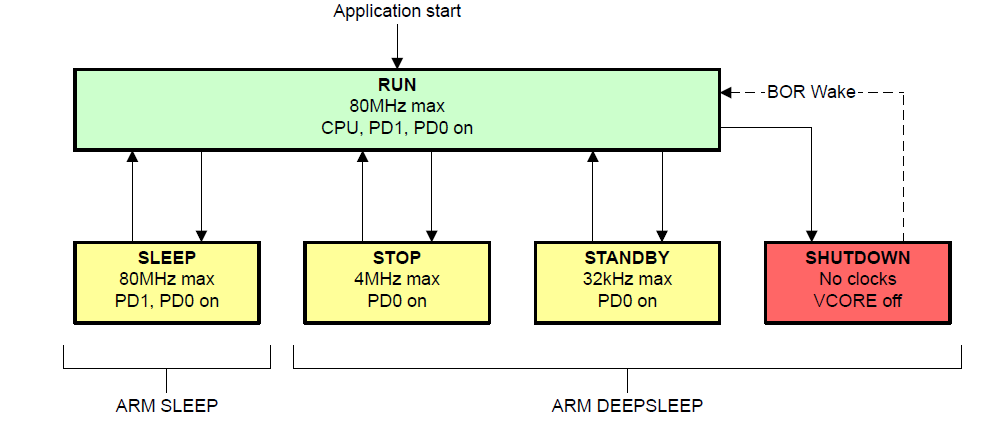
There are five power modes in MSPM0 devices: RUN, SLEEP, STOP, STANDBY and SHUTDOWN. Figure 1-2 shows the interaction between the modes.
PD1 is only enabled in RUN and SLEEP mode. While PD1 is disabled in STOP and STANDBY mode, the CPU registers, SRAM, and peripheral MMR configuration registers are maintained in retention such that these modules are available to resume operation immediately when STOP or STANDBY modes are exited.
PD0 is powered in all modes except SHUTDOWN mode and can be thought of as an "always-on" domain. PD0 runs from ULPCLK with a max frequency of 40MHz in RUN and SLEEP mode, 4MHz in STOP mode, and 32kHz in STANDBY mode.

Figure 1-2 MSPM0G Series Operation Modes
Figure 1-3 defines how to configure the relevant policy bits for each operating mode. All values are indicated in binary format. A dash (-) indicates that the particular policy bit is a don't care for the specified operating mode. For the detailed description of these low power modes, please refer to 2.1PMCU Overview of MSPM0 G-Series 80MHz Microcontrollers Technical Reference Manual (Rev. A) (ti.com).

Figure 1-3 Operation Mode Policy Bit Configuration
- RUN Mode
In RUN mode, the CPU is active executing code and every peripheral can be enabled.
There are three RUN mode policy options: RUN0, RUN1, and RUN2.
The RUN mode is active after clock configuration by DL_SYSCTL_setPowerPolicyRUNxSLEEPx() API function in MSPM0 SDK, where x is selected from 0/1/2, representing three RUN mode policy options.
- SLEEP Mode
In SLEEP mode, the CPU is disabled (clock gated) but otherwise the device configuration is the same as RUN. So the configuration API function of SLEEP mode is as same as RUN mode. The difference is that, SLEEP mode disables CPU running by WFI/WFE instruction.
- STOP Mode
In STOP mode, the CPU, SRAM, and PD1 peripherals are disabled and in retention (if applicable). PD0 peripherals are available with a max ULPCLK frequency of 4MHz. SYSOSC can run at higher frequencies to support ADC, OPA, or COMP operation, but ULPCLK is automatically limited to the 4MHz SYSOSC output by SYSCTL. High speed oscillators (SYSPLL, HFXT, HFCLK_IN) are automatically disabled.
There are three policy options for STOP mode: STOP0, STOP1, and STOP2.
The STOP mode is configured by DL_SYSCTL_setPowerPolicySTOPx() API function in MSPM0 SDK, where x is selected from 0/1/2, representing three STOP mode policy options. STOP mode configuration is triggered to be valid by WFI/WFE instruction.
- STANDBY Mode
In STANDBY mode, the CPU, SRAM, and PD1 peripherals are disabled and in retention. PD0 peripherals, with the exception of the ADC, 12-bit DAC, and OPA, are available with a maximum ULPCLK frequency of 32kHz. High-speed oscillators (SYSPLL, HFXT, HFCLK_IN) and SYSOSC are disabled.
There are two policy options for STANDBY mode: STANDBY0 and STANDBY1.
The STANDBY mode is configured by DL_SYSCTL_setPowerPolicySTANDBYx() API function in MSPM0 SDK, where x is selected from 0/1, representing two STANDBY mode policy options. STANDBY mode configuration is triggered to be valid by WFI/WFE instruction.
- SHUTWODN Mode
In SHUTDOWN mode, no clocks are available. The core regulator is completely disabled and all SRAM and register contents are lost. The BOR and bandgap circuit are disabled.
The device can wake through a wake-up capable IO, a debug connection or NRST.