SLAAEO9 October 2024 MSPM0C1103 , MSPM0C1103-Q1 , MSPM0C1104 , MSPM0C1104-Q1 , MSPM0G1105 , MSPM0G1106 , MSPM0G1107 , MSPM0G1505 , MSPM0G1506 , MSPM0G1507 , MSPM0G3105 , MSPM0G3105-Q1 , MSPM0G3106 , MSPM0G3106-Q1 , MSPM0G3107 , MSPM0G3107-Q1 , MSPM0G3505 , MSPM0G3505-Q1 , MSPM0G3506 , MSPM0G3506-Q1 , MSPM0G3507 , MSPM0G3507-Q1 , MSPM0G3519 , MSPM0L1105
2 MSPM0 System Power Consumption Measurement
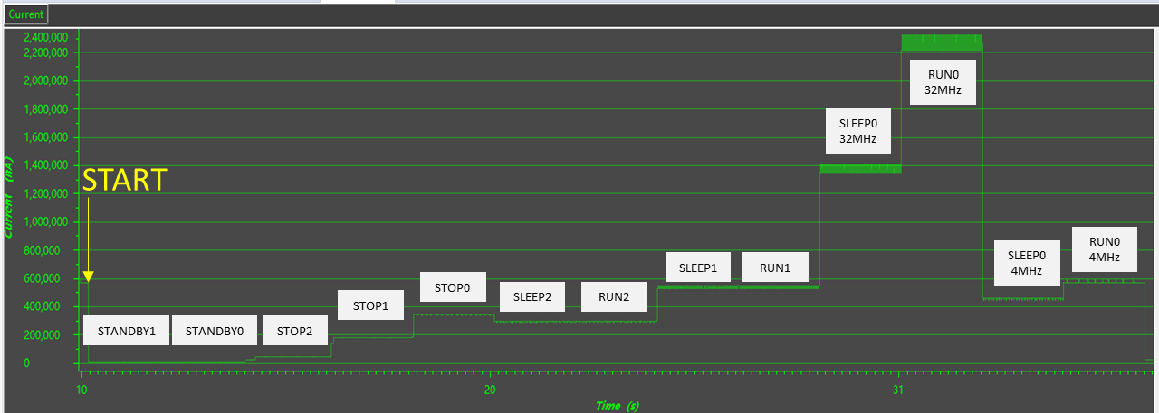
Table 2-1 shows the hardware/software configuration and test results of MSPM0G350x system power consumption measurement under different low-power mode. The power consumption of MSPM0 without any peripheral enabled is strongly related to the clock configuration. For reference, SYSOSC, MCLK, ULPCLK is listed under a different low-power policy.
| Low-Power Mode | Configuration | Current | |||
|---|---|---|---|---|---|
| Low-Power Policy | SYSOSC | MCLK | ULPCLK | ||
| Hardware |
|
||||
| Software |
|
||||
| Low Power Policy | Standby1 + WFI | DIS | DIS | 32kHz | 1.5uA |
| Standby0 + WFI | DIS | DIS | 32kHz | 1.9uA | |
| Stop2 + WFI | DIS | DIS | 32kHz | 46uA | |
| Stop1 + WFI | 4MHz | DIS | 4MHz | 182uA | |
| Stop0 + WFI | 32MHz | DIS | 4MHz | 346uA | |
| RUN2SLEEP2 + WFI | DIS | 32kHz | 32kHz | 293uA | |
| RUN2SLEEP2 + while (1) {} | DIS | 32kHz | 32kHz | 294uA | |
| RUN1SLEEP1 + WFI | 32MHz | 32kHz | 32kHz | 535uA | |
| RUN1SLEEP1+ while (1) {} | 32MHz | 32kHz | 32kHz | 536uA | |
| RUN0SLEEP0 + WFI (SYSOSC=32MHz) | 32MHz | 32MHz | 32MHz | 1.36mA | |
| RUN0SLEEP0 + while (1) {} (SYSOSC=32MHz) | 32MHz | 32MHz | 32MHz | 2.22mA | |
| RUN0SLEEP0 + WFI (SYSOSC=4MHz) | 4MHz | 4MHz | 4MHz | 456uA | |
| RUN0SLEEP0 + while (1) {} (SYSOSC=4MHz) | 4MHz | 4MHz | 4MHz | 569uA | |

There are several conclusions according to the power consumption test results above:
- The RUN mode and SLEEP mode configurations are valid without WFI/WFE instruction;
- When CPU runs at frequency of 32kHz, the RUN1/RUN2 mode has close power consumption with SLEEP1/SLEEP2 mode because of low running clock frequency.