SLAU841A October 2020 – October 2022 DAC43701 , DAC43701-Q1 , DAC53701 , DAC53701-Q1
2.1.2 Software Installation
Before software installation, make sure that the DAC53701EVM is not connected to the computer.
The software can be downloaded from the device product folders. After the software is downloaded, navigate to the download folder, and run the DAC53701EVM software installer executable.
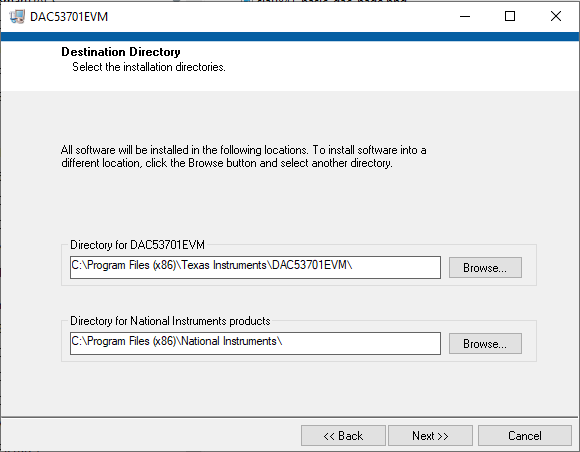
When the DAC53701EVM software is launched, an installation dialog window opens and prompts the user to select an installation directory. Figure 2-1 shows that the software path defaults to C:\Program Files (x86)\Texas Instruments\DAC53701EVM.
 Figure 2-1 Software Installation Path
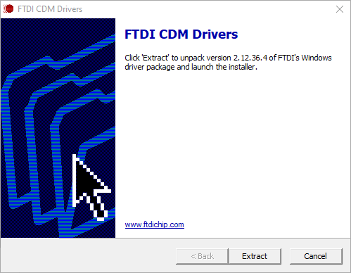
The software installation also installs the FTDI USB drivers, and automatically copies the required LabVIEW™ software files and drivers to the computer. The FTDI USB drivers install in a second executable. Figure 2-2 shows the window that is automatically launched after the DAC53701EVM software installation is complete.
 Figure 2-2 FTDI USB Drivers