SLAU892A March   2023  – June 2024 AFE11612-SEP


  1.   1
  2.   Description
  3.   Features
  4.   4
  5. 1Evaluation Module Overview
    1. 1.1 Introduction
    2. 1.2 Kit Contents
    3. 1.3 Specification
    4. 1.4 Device Information
  6. 2Hardware
    1. 2.1 Hardware Setup
      1. 2.1.1 Electrostatic Discharge Caution
      2. 2.1.2 Power Configurations and Jumper Settings
      3. 2.1.3 Connecting the Hardware
    2. 2.2 Hardware Description
      1. 2.2.1 Theory of Operation
        1. 2.2.1.1 Signal Definitions
  7. 3Software
    1. 3.1 Software Setup
      1. 3.1.1 Operating Systems
      2. 3.1.2 Software Installation
    2. 3.2 Software Description
      1. 3.2.1 Starting the Software
      2. 3.2.2 Software Features
        1. 3.2.2.1 High Level Configuration Page
          1. 3.2.2.1.1 DACs Subpage
          2. 3.2.2.1.2 ADCs Subpage
          3. 3.2.2.1.3 Alarms Subpage
          4. 3.2.2.1.4 GPIO + Temp Subpage
        2. 3.2.2.2 Low Level Configuration Page
  8. 4Hardware Design Files
    1. 4.1 Schematics
    2. 4.2 PCB Layout
    3. 4.3 Bill of Materials
  9. 5Additional Information
    1. 5.1 Trademarks
  10. 6Related Documentation from Texas Instruments
  11. 7Revision History
GPIO + Temp Subpage

Figure 4-9 shows the GPIO + Temp subpage. The GPIO + Temp page allows the user to view and access the AFE11612-SEP registers related to the three temperature monitoring functions. Press the READ TEMP button to enable a temperature conversion and update the temperature value for all temperature functions in degrees Celsius (°C) and hexadecimal. Additionally, these functions can be modified by adjusting the corresponding Hysteresis and nFactor values.
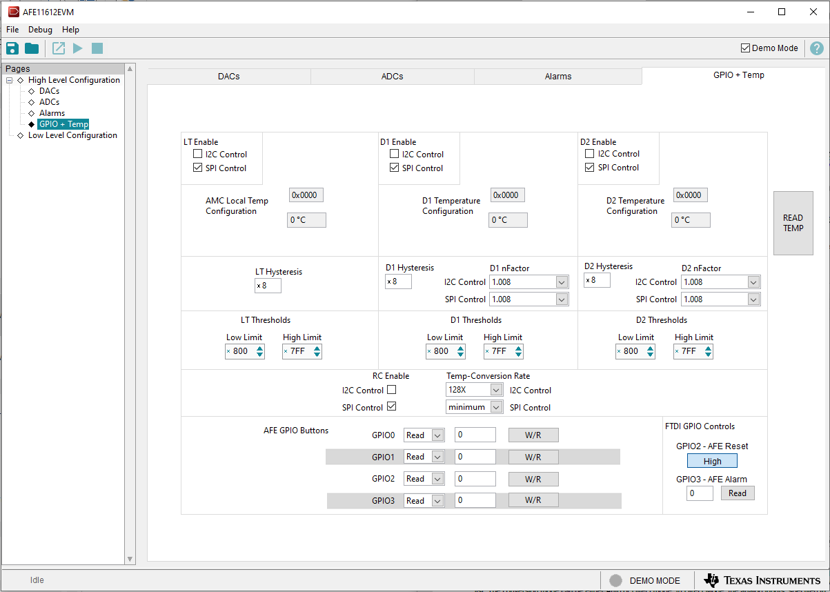
AFE11612EVM GPIO + Temp
                                        Subpage Figure 3-9 GPIO + Temp Subpage