SLAU932 October 2024 AMC8V208
3.2.2.2 Low Level Configuration Page
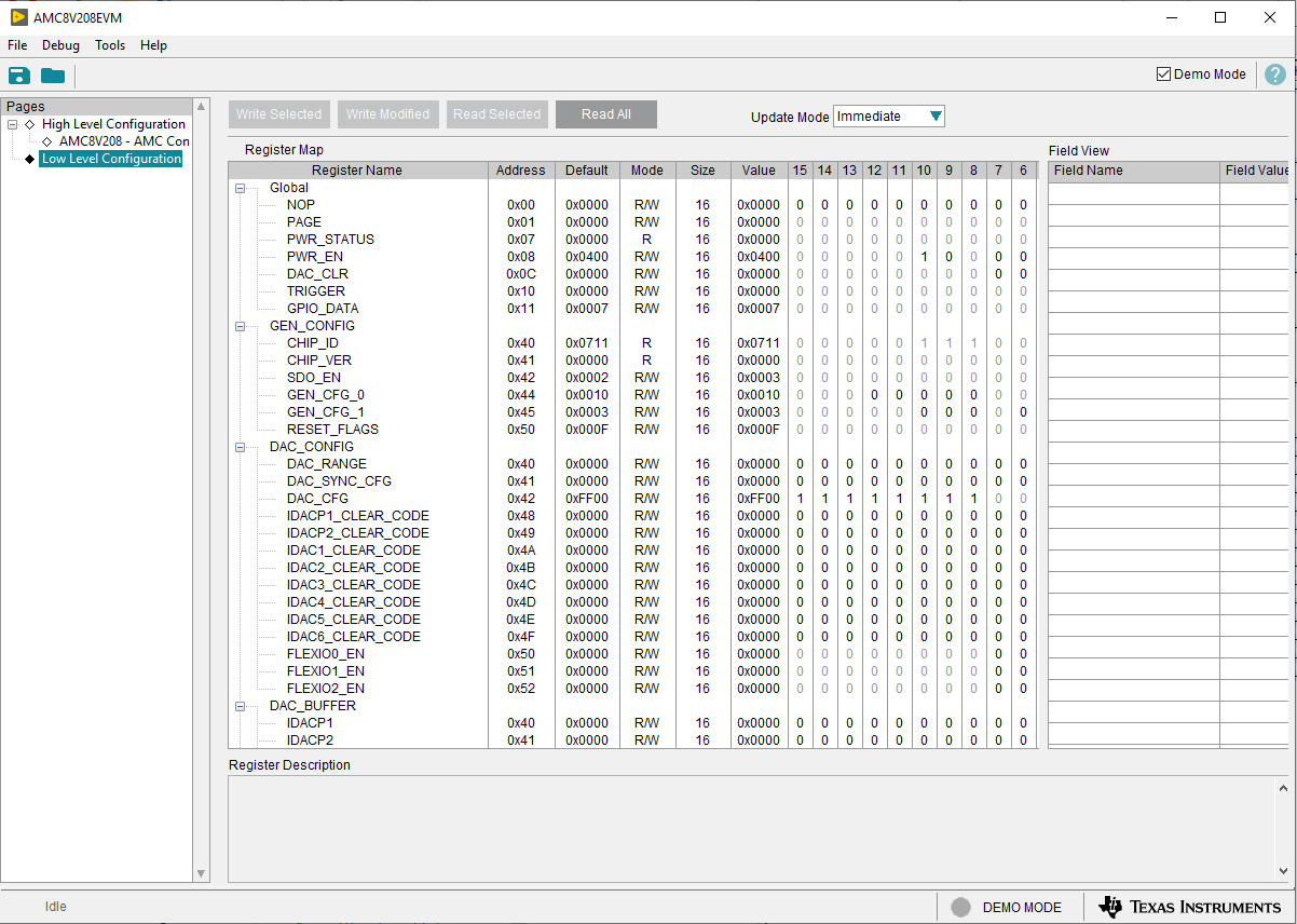
The Low Level Configuration page of the AMC8V208EVM GUI is shown in Figure 3-4. This page allows access to low-level communication directly with the respective AMC8V208 device registers.
The Register Map section in the center of the page lists all the registers, grouped by the pages in the device. The GUI automatically addresses the correct page based on the register selected. Selecting a register on the Register Name list shows a description of the values in that register, as well as information on the register address, default value, size, and current value. Data are written to the registers by entering a value in the value column of the GUI.
 Figure 3-4 Low Level Configuration
Page
Figure 3-4 Low Level Configuration
PageTo store the values of the register map locally, select Save Configuration under the File menu option. The stored configuration files can be recalled and loaded by selecting Open Configuration.
The four configuration buttons provided on the Low Level Configuration page that allow the user to read from and write to the device registers are shown in Figure 3-5.
- Write Selected
- Write Modified
- Read Selected
- Read All
The Write Modified button is enabled only in Deferred Update Mode. Deferred Update Mode initiates a write operation only when the Write Selected or Write Modified buttons are pressed. By default, Immediate Update Mode is selected for the Low Level Configuration page write operations.
The AMC8V208 SDO pin must be enabled in the SDO_EN register before reading any device registers.
 Figure 3-5 Low Level Configuration Page
Options