SLDA058 March   2021 TUSS4470


  1.   Trademarks
  2. 1Review of Ultrasonic Sensing Range Performance Factors
    1. 1.1 Physical Parameters
    2. 1.2 Transducer Characteristics
    3. 1.3 AFE Device Configuration
  3. 2Methods Overview
    1. 2.1 Introduction
    2. 2.2 Hardware Configuration
      1. 2.2.1 Transducers
      2. 2.2.2 Experimental Setup: Air-Coupled Level Sensing
      3. 2.2.3 Experimental Setup: Water-Coupled Level Sensing
      4. 2.2.4 TUSS4470 EVM Hardware Configuration
      5. 2.2.5 TDC1000-C2000EVM Hardware Configuration
    3. 2.3 Firmware Configuration
      1. 2.3.1 TUSS4470 Power Configuration
      2. 2.3.2 TUSS4470 220 kHz Configuration
      3. 2.3.3 TDC1000 220kHz Configuration
      4. 2.3.4 TDC1000 220kHz Configuration
      5. 2.3.5 TDC1000 1 MHz
  4. 3Short Range Air-Coupled Test Results
    1. 3.1 TUSS4470
    2. 3.2 TDC1000
  5. 4Mid-Range Air-Coupled Test Results
    1. 4.1 TUSS4470
      1. 4.1.1 Concept
      2. 4.1.2 TUSS4470 35 V Results
    2. 4.2 TDC1000
  6. 5Short Range Water-Coupled Test Results
    1. 5.1 TUSS4470
    2. 5.2 TDC1000
  7. 6Resistive Damping Device Comparison
    1. 6.1 TUSS4470
    2. 6.2 TDC1000
  8. 7Summary
  9. 8References
  10.   A Appendix A
    1.     A.1 TUSS4470: Filter Capacitor Selection
    2.     A.2 TUSS4470: Shematic
  11.   B Appendix B
    1.     B.1 TDC1000 Misc.
    2.     B.2 TDC1000-C2000EVM Schematic

Experimental Setup: Water-Coupled Level Sensing

The piezo disc transducer was mounted to the bottom of the small plexiglass tank shown in Figure 2-3, following the procedure described in How to Select and Mount Transducers in Ultrasonic Sensing for Level Sensing and Fluid ID.
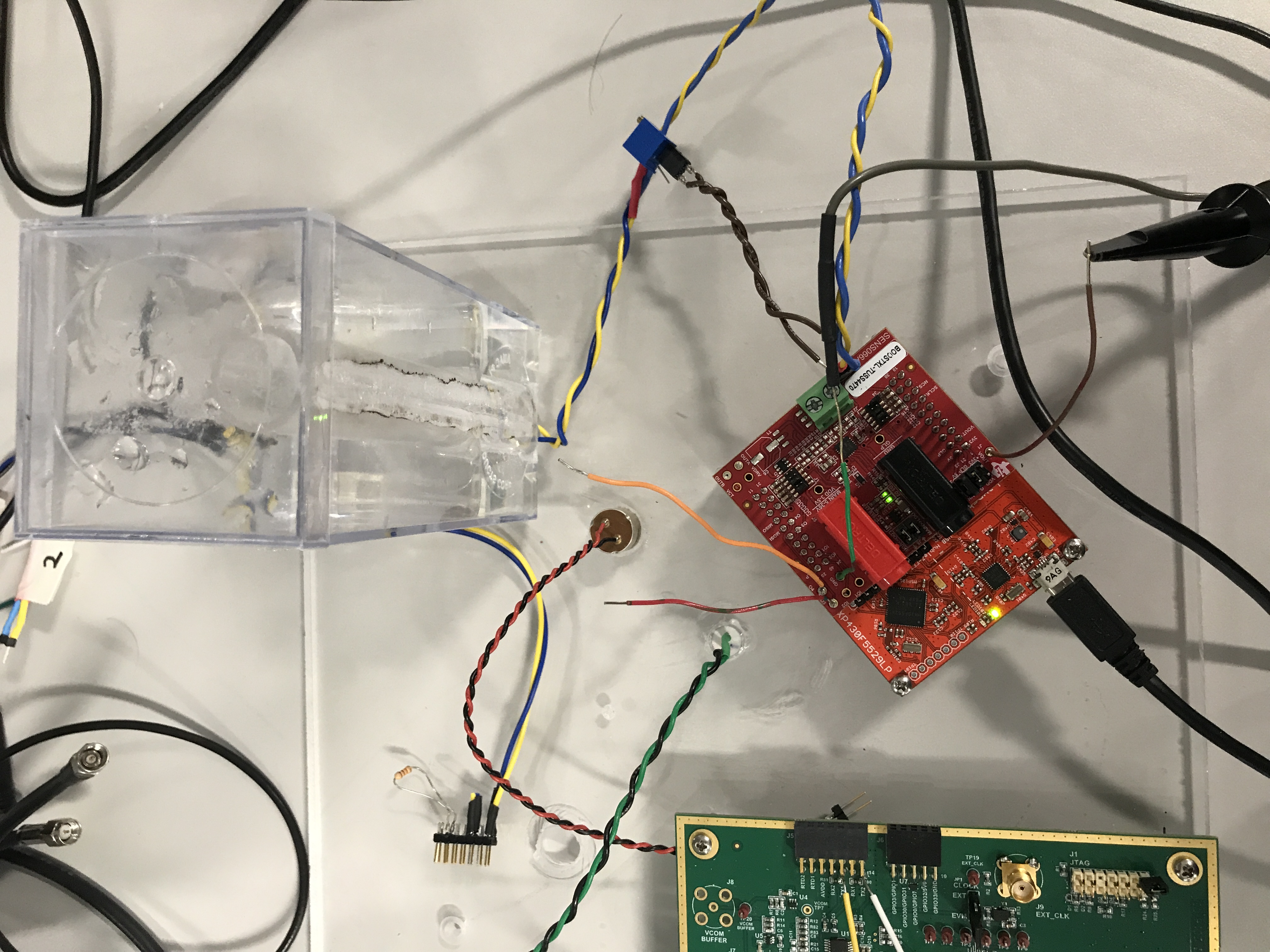
GUID-20210308-CA0I-SW2L-J4WP-55T27NVNTNNG-low.jpg Figure 2-3 Short-Range Water-Coupled Level Sensing Test Environment