-
Robust Isolated RS-485 Enables New Industrial Applications
Robust Isolated RS-485 Enables New Industrial Applications
Application Brief
RS-485 introduction
RS-485 is one of the most widely used wired interface for industrial long-haul networks. TIA/EIA-485-A standard defines the physical layer of the RS-485 interface. End applications use RS-485 interface coupled with protocol such as Profibus, Modbus or BACnet. The main benefits of this interface include:
- Balanced differential signaling allows for rejection of common mode noise and facilitates communications over long distances in noisy industrial environments.
- Support of –7 to 12 V wide common mode range allows for multipoint data transmission between nodes located at different ground potential difference.
- Data rates up to 50 Mbps at short distances or communications distance up to 1000 meters at slower data rates is possible.
Applications for RS-485 include Energy Meters, Grid Protection relay, Solar inverter, Factory automation, Motor control and Heating, ventilation, air conditioning (HVAC) systems.
Isolated RS-485 in end applications
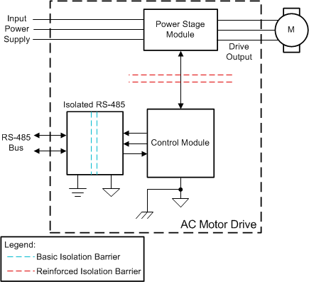
Figure 1-1 shows a typical block diagram of AC Motor drive:
 Figure 1-1 AC Motor Drive Block
Diagram
Figure 1-1 AC Motor Drive Block
DiagramA control module typically communicates to a Programmable logic controller (PLC) over RS-485 physical layer. It is common in factory environments that the ground potential difference (GPD) between the AC drive and the PLC can be much higher than the common mode voltage range suggested in the RS-485 standard. Galvanic isolation is usually introduced in the signal and supply lines of the RS-485 bus transceiver in the drive system to break to ground loop. This technique allows to transfer data between the drive and the PLC in the presence of huge GPD. In this case, basic isolation for RS-485 link is sufficient since high voltage in power stage is already isolated from control stage. Electrical fast transient (EFT) on the RS-485 link also becomes a key concern because of inductive switching.
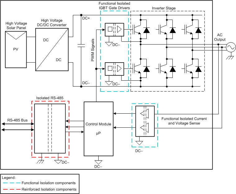
Figure 1-2 shows typical implementation of a Solar Inverter. RS-485 serves as a communication channel between the Inverter and the control station. The configuration and performance parameters are transferred between the Control station and the inverter over the RS-485 link.
 Figure 1-2 Solar Inverter
Implementation
Figure 1-2 Solar Inverter
ImplementationIn Figure 1-2, control module that drives the inverter stage is referenced to High voltage DC-. RS-485 link is interfaced on a human accessible connector and must be protected from high voltage to account for operator safety, mandating reinforced isolation. With increasing demand for higher conversion efficiency, solar inverters are being designed with higher DC link voltages up to 1500 V. This translates to need for higher working voltage for the isolation barrier for RS-485 communication.
Other performance considerations
Other than isolation, key requirements of the systems requiring Isolated RS-485 are:
- Differential output voltage swing: Larger differential swing on the RS-485 interface allows for greater signal-to-noise ratio (SNR) and longer reach. PROFIBUS compliant transceivers support VOD ≥ 2.1 V and are used in several drive and factory automation systems.
- Robustness to transient noise: Wired interfaces running on factory floors or outdoor environments are subjected to transient noise such as electrostatic discharge, lighting strike or Electrical fast transient. A robust RS-485 link is expected to survive these harsh transients and to enable the data transfer with minimum to no data loss.
- Glitch free power up/power down for hot plug: In an RS-485 network, it is important that existing communications on the bus between two nodes must not be disturbed when a new node is swapped in or out of the network.
New Isolated RS-485
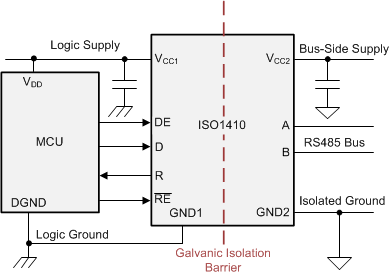
The ISO1410 is the latest Isolated RS-485/Profibus transceiver from Texas Instruments with all the above mentioned capabilities. Figure 1-3 shows the typical application schematic. This device can operate from 1.71 V to 5.5 V on the logic side, allowing to be interfaced with low voltage FPGAs and ASICs. Wide bus side supply voltage from 3 to 5.5 V eliminates the need for regulated supply voltage. This device family is fully characterized over a wide operating ambient temperature range from –40°C to +125°C and is available in 16-pin wide body SOIC package (8-mm creepage/clearance).
 Figure 1-3 Application Schematic
The SiO2 isolation barrier supports isolation withstand voltage of 5 kVRMS for 60 s per UL1577. It is available in basic and reinforced isolation options as shown in Table 1-1.
| Feature | ISO1410 | ISO1410B |
|---|---|---|
| Protection level | Reinforced | Basic |
| Surge test voltage per VDE | 10000 VPK | 6000 VPK |
| Isolation rating per UL | 5000 VRMS | 5000 VRMS |
| Working voltage per VDE | 1000 VRMS /1500 VPK | 1000 VRMS /1500 VPK |
SiO2 based isolation barrier offers superior isolation performance that is resistant to temperature and humidity. Isolation working voltage of 1500 Vpk for 40 years lifetime is highest in the industry and allows to be used in 1500 V Solar Inverter and 690 VAC Motor drive systems.
Other differentiating features of ISO1410 are:
- On chip 16 kV IEC ESD (contact discharge) and 4 kV IEC EFT protection improves robustness against transient events. With proper system design and utilization of isolation barrier, external protection components on bus can be eliminated and Level 4 EMC protection can be achieved.
- Common mode transient immunity of minimum 85 kV/us is highest in the industry. This ensures reliable data communication across isolation barrier in the presence of fast-changing common mode noise.
- 1/8 Unit load to support up to 256 nodes on the bus.
- Receiver Failsafe provides a logic high output under Bus Short, open or idle conditions. This also eliminates 2 biasing resistors required in traditional isolated transceivers.
Conclusion
ISO1410 device offers integration along with superior system level performance. This device has highest working voltage (1500Vpk) in the industry and is capable to tolerate very high levels of IEC ESD and EFT.
These features make it a compelling solution for most industrial applications including Solar inverter and Motor drives. This device addresses key concerns often faced by end equipment designers in isolating RS-485 ports and enables communication in harsh industrial environments.
| Device | Optimized Parameters | Performance Trade-Off |
|---|---|---|
| ISOW1412 | Optimized Parameters: 5-kVRMS, 500-kbps isolated RS-485 transceiver with integrated DC/DC converter | Performance Trade-off: Integrated low radiated emissions DC/DC converter reduces board space and simplifies designs |
| ISOW1432 | Optimized Parameters: 5-kVRMS, 12-Mbps isolated RS-485 transceiver with integrated DC/DC converter | Performance Trade-off: Integrated low radiated emissions DC/DC converter reduces board space and simplifies designs |
IMPORTANT NOTICE AND DISCLAIMER
TI PROVIDES TECHNICAL AND RELIABILITY DATA (INCLUDING DATASHEETS), DESIGN RESOURCES (INCLUDING REFERENCE DESIGNS), APPLICATION OR OTHER DESIGN ADVICE, WEB TOOLS, SAFETY INFORMATION, AND OTHER RESOURCES “AS IS” AND WITH ALL FAULTS, AND DISCLAIMS ALL WARRANTIES, EXPRESS AND IMPLIED, INCLUDING WITHOUT LIMITATION ANY IMPLIED WARRANTIES OF MERCHANTABILITY, FITNESS FOR A PARTICULAR PURPOSE OR NON-INFRINGEMENT OF THIRD PARTY INTELLECTUAL PROPERTY RIGHTS.
These resources are intended for skilled developers designing with TI products. You are solely responsible for (1) selecting the appropriate TI products for your application, (2) designing, validating and testing your application, and (3) ensuring your application meets applicable standards, and any other safety, security, or other requirements. These resources are subject to change without notice. TI grants you permission to use these resources only for development of an application that uses the TI products described in the resource. Other reproduction and display of these resources is prohibited. No license is granted to any other TI intellectual property right or to any third party intellectual property right. TI disclaims responsibility for, and you will fully indemnify TI and its representatives against, any claims, damages, costs, losses, and liabilities arising out of your use of these resources.
TI’s products are provided subject to TI’s Terms of Sale (www.ti.com/legal/termsofsale.html) or other applicable terms available either on ti.com or provided in conjunction with such TI products. TI’s provision of these resources does not expand or otherwise alter TI’s applicable warranties or warranty disclaimers for TI products.
Mailing Address: Texas Instruments, Post Office Box 655303, Dallas, Texas 75265
Copyright © 2022, Texas Instruments Incorporated