-
How to Isolate RS-485 for Smallest Size and Highest Reliability
How to Isolate RS-485 for Smallest Size and Highest Reliability
How to Isolate RS-485 for Smallest Size and Highest Reliability
Galvanic Isolation for the RS-485 Port
RS-485 has been the industry’s most used wired communications interface for more than decades. Balanced differential signaling of RS-485 allows for rejection of common mode noise and facilitates communications over long distances in noisy industrial environments. RS-485 is a common communications port in most industrial applications such as factory automation, protection relay, energy meter, motor drives and building automation.
TIA/EIA-485-A standard defines that the compliant transceivers must work with ±7 V ground potential difference (GPD). As shown in Figure 1-1, common mode voltage on receiver bus pins (Vcm) is a sum of GPD, driver output common mode voltage (Voc) and any common mode coupled noise (Vn) to the bus pins. As the communication distance between the nodes increases leading to higher GPD or as the industrial environment becomes noisier thereby coupling more common mode noise on the bus, the common mode voltage on receiver bus pins moves out of its recommended operating condition. This can lead to data corruption or damage to the transceiver.
 Figure 1-1
 As shown in Figure 1-2, galvanic isolation in signal and power path for the RS-485 transceiver is a solution to this problem. Since the isolation barrier impedance (>1012 ohm) is much larger than the RS-485 receiver input impedance, any voltage with respect to GND2 appears primarily across the isolation barrier. Isolation allows signal transfer to happen between receiving MCU and floating transceiver while handling large ground potential difference between GND1 and GND2.
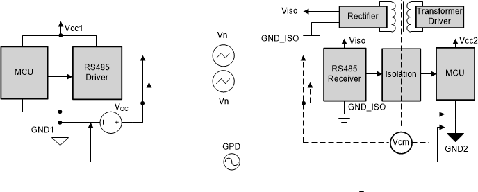 Figure 1-2
 Traditional Solution
Historically, system designers have used optocoupler based solutions to enable communication between nodes with large GPDs. A typical implementation, as shown in Figure 1-3, requires an RS-485 transceiver, 2 high speed optocouplers to transmit and receive data, a low speed optocoupler for direction control, 2 Schmitt buffers to drive the LED of the optocoupler, 1 Schmitt trigger to clean up the slow edges from low speed optocoupler, a few resistors for correct biasing and a few bypass capacitors.
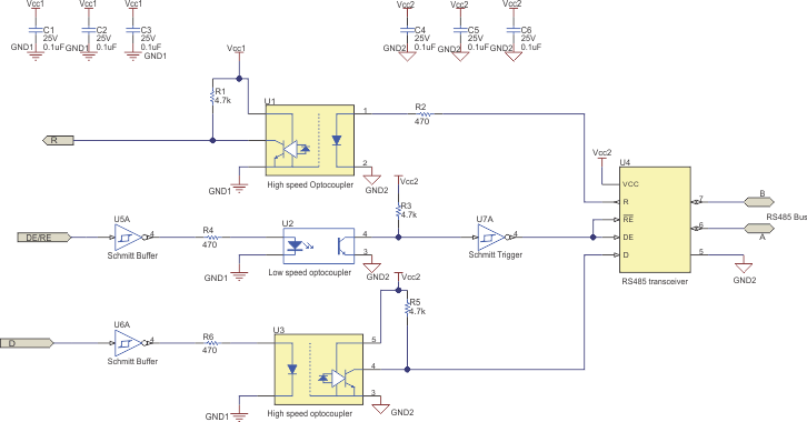 Figure 1-3
 The challenge with the optocoupler based solution is the high number of external components needed to achieve isolation for the RS-485 port, which increases board area and opens potential reliability issues. A SiO2 based integrated isolated RS-485 solution provides a compact and reliable alternative to the optocoupler solution for system designers in need of compact design with lower failures in time (FIT) rates.
Integrated Isolated RS-485 Transceivers
TI offers multiple isolated RS-485 transceivers based on different isolation rating for various end-applications. ISO1410 is a noise immune transceiver with integrated IEC ESD and EFT protection in a industry standard 16-SOIC package. ISO1410 offers 5 kVRMS isolation rating per UL 1577 and 1500 Vpk of isolation working voltage per VDE. Some applications require only basic isolation to communicate between nodes with ground potential differences higher than ± 7 V that is defined by the standard. ISO1500 integrates the complete functionality of an isolated RS-485 port in a miniature SSOP-16 package. ISO1500 offers 3 kVrms isolation rating per UL 1577 and 566 Vpk of isolation working voltage per VDE.
Solution Size Comparison
The figures below show the layout comparison between an optocoupler based solution (Figure 1-4), a commonly available 16-SOIC based isolated RS-485 solution (Figure 1-5) and solution using the ISO1500 (Figure 1-6). ISO1500 reduces the solution board area by up to 85% compared to the optocoupler solution and by up to 50% compared to 16-SOIC based solution.
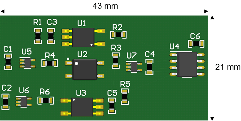 Figure 1-4
 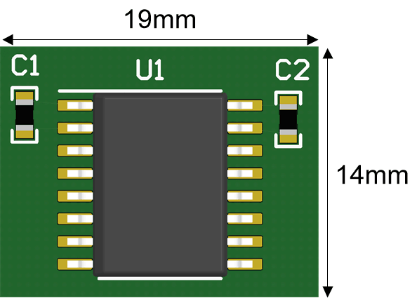 Figure 1-5
 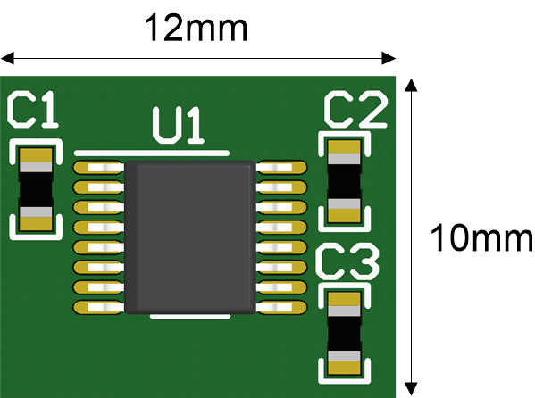 Figure 1-6
 The tiny package and robust functionality of the ISO1500 provide a compelling solution across industrial applications for designs that need ground loop basic isolation for RS-485 communications port and have limited board space available.
Reliability Comparison
Other than the PCB space savings, below are some of the other advantages that ISO1500 and ISO1410 provide over optocoupler based solution:
- Reliability of isolation barrier: ISO1500 is based on TI’s SiO2 isolation technology where the high voltage capacitors made with SiO2 dielectric provide a high level of isolation. High voltage capacitors are constructed in a well-controlled semiconductor process and offer very low part-to-part variation. Also, the isolation barrier lifetime is well defined by the time dependent dielectric breakdown (TDDB) technique. On the other hand, optocouplers have a lot of manufacturing variability and no defined technique in the standard to calculate lifetime of the device. A detailed explanation of lifetime reliability for TI’s SiO2 isolation technology can be found in the white paper: Enabling high voltage signal isolation quality and reliability
- Reliable operation at higher ambient temperatures: Most optocouplers are rated up to 85°C max. There are optocouplers available in the market rated for 105°C, but they are rare and expensive. ISO1500 is characterized over an extended industrial temperature range of –40 to 125°C enabling applications such as motor drives to have lot of margin from the device recommended maximum ambient temperature. This enables reliable operation in the presence of high power dissipation circuitry, such as the insulated-gate bipolar transistor (IGBT) power stage, closer to the RS-485 port.
- Reliable operation in the presence of transient noise: Optocouplers available in the market have typical CMTI of 15 kV/us to 25 kV/us. This means if noise between side 1 to side 2 is varying faster than 15-25 kV/us, data communication across the isolation barrier may get corrupted. ISO1500 offers typical CMTI of 100 kV/us. This is a direct measure of reliable data transmission and better noise immunity. ISO1500 is also robust to transient noise as it integrates bus side protection circuitry for HBM ESD, IEC ESD and IEC EFT.
Conclusion
Reliable communication over long distances in the presence of large GPD is an important consideration while designing an RS-485 port. Traditional solutions with optocouplers consume a considerable amount of PCB board space in a world where more and more applications are moving towards miniaturization.
ISO1500 is available in a tiny 4.90 mm x 3.90 mm SSOP package and requires just 3 external components in the form of bypass capacitors on the supply pins for full functionality compared to 19 components required for optocoupler based implementation. Compact solution size along with superior isolation performance and transient-noise immunity makes this device a compelling option for space constrained industrial applications.
| Device | Optimized Parameters | Performance Trade-Off |
|---|---|---|
| ISO1410 | 5-kVrms Isolation, IEC ESD, IEC EFT | 16-SOIC Package |
| ISOW1412 | 5kVrms, 500kbps isolated RS-485 transceiver with integrated DC/DC converter | Integrated low radiated emissions DC/DC converter reduces board space and simplifies designs |
| ISOW1432 | 5kVrms, 12Mbps isolated RS-485 transceiver with integrated DC/DC converter | Integrated low radiated emissions DC/DC converter reduces board space and simplifies designs |
| Robust Isolated RS-485 Enables New Industrial Applications |
| How to Isolate Signal and Power For an RS-485 System |
IMPORTANT NOTICE AND DISCLAIMER
TI PROVIDES TECHNICAL AND RELIABILITY DATA (INCLUDING DATASHEETS), DESIGN RESOURCES (INCLUDING REFERENCE DESIGNS), APPLICATION OR OTHER DESIGN ADVICE, WEB TOOLS, SAFETY INFORMATION, AND OTHER RESOURCES “AS IS” AND WITH ALL FAULTS, AND DISCLAIMS ALL WARRANTIES, EXPRESS AND IMPLIED, INCLUDING WITHOUT LIMITATION ANY IMPLIED WARRANTIES OF MERCHANTABILITY, FITNESS FOR A PARTICULAR PURPOSE OR NON-INFRINGEMENT OF THIRD PARTY INTELLECTUAL PROPERTY RIGHTS.
These resources are intended for skilled developers designing with TI products. You are solely responsible for (1) selecting the appropriate TI products for your application, (2) designing, validating and testing your application, and (3) ensuring your application meets applicable standards, and any other safety, security, or other requirements. These resources are subject to change without notice. TI grants you permission to use these resources only for development of an application that uses the TI products described in the resource. Other reproduction and display of these resources is prohibited. No license is granted to any other TI intellectual property right or to any third party intellectual property right. TI disclaims responsibility for, and you will fully indemnify TI and its representatives against, any claims, damages, costs, losses, and liabilities arising out of your use of these resources.
TI’s products are provided subject to TI’s Terms of Sale (www.ti.com/legal/termsofsale.html) or other applicable terms available either on ti.com or provided in conjunction with such TI products. TI’s provision of these resources does not expand or otherwise alter TI’s applicable warranties or warranty disclaimers for TI products.
Mailing Address: Texas Instruments, Post Office Box 655303, Dallas, Texas 75265
Copyright © 2022, Texas Instruments Incorporated