SLLA497 September 2020 TMS320F28P550SG , TMS320F28P550SJ , TMS320F28P559SJ-Q1
3.4 Three-phase Vienna PFC
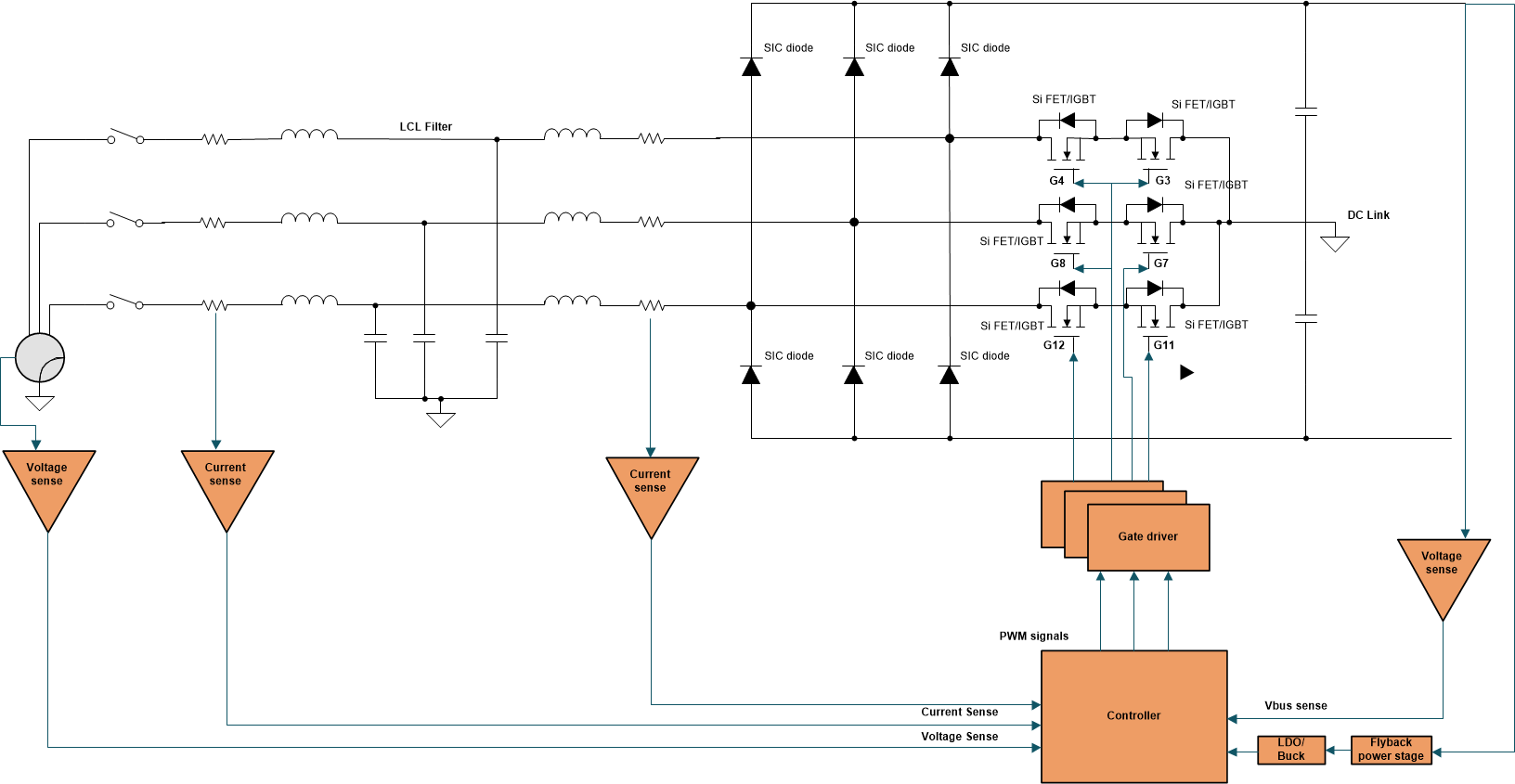
The Vienna rectifier power topology, shown in Figure 3-5, is used in high-power, three-phase power factor correction applications. The Vienna rectifier is popular due to its operation in continuous conduction mode (CCM), inherent multilevel switching (three level), and reduced voltage stress on the power devices. Both hysteresis-based and sine triangle based controllers have been used for Vienna rectifiers, hence it is relatively simpler to control due to the smaller amount of PWMs required for this topology. One of the drawbacks of this topology is that it only supports unidirectional mode power transfer from the grid to the DC side. Vienna Rectifier is characterized by a relatively small overall volume or a high power density as it requires approximately only half of the inductance for the boost inductors compared to the two level rectifiers discussed in Section 3.3. The multilevel signature of output voltage also provides a better THD performance. Opposed to the two-level PFC, the Vienna Rectifier enables high efficiency at elevated switching frequencies with Si MOSFETs or 600-V to 650-V IGBTs and SiC Schottky diodes as a result of its three-level characteristic and does not require advanced 1200-V SiC power FETs to lower the switching losses. The Vienna Rectifier-Based Three Phase Power Factor Correction Reference Design Using C2000 MCU TI reference design contains details on the implementation of this converter.
 Figure 3-5 Vienna Rectifier.