SLLU338 August 2021 MCF8316A
4.4 LED Lights
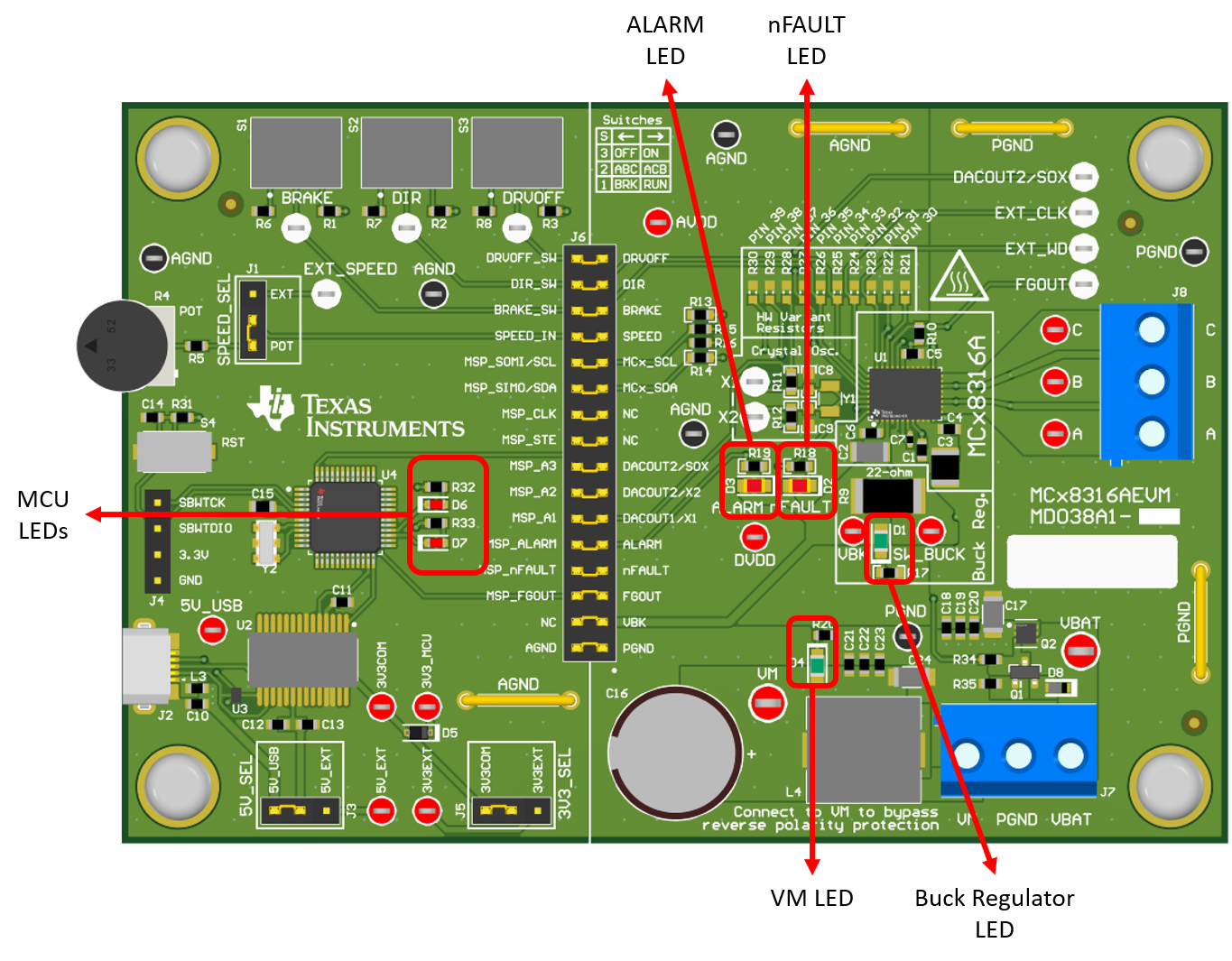
The MCF8316AEVM has 5 status LEDs implemented that provide the status of power supplies and functionalities of the evaluation module. By default, the VM LED and 3.3 V Buck LEDs will light up when the board is powered and the program has been flashed onto the microcontroller. Table 4-1 shows LED descriptions including those that are on during power up in bold and Figure 4-5 shows the locations of the LEDs.
Table 4-1 Description of MCF8316AEVM
LEDs (default in bold after powerup)
| Designator | Name | Color | Description |
|---|---|---|---|
|
D1 |
Buck Regulator |
Green |
Internal buck regulator is voltage output |
|
D2 |
nFAULT |
Red |
Lights up when fault condition has occurred on MCF8316A |
|
D3 |
ALARM |
Red |
Lights up when alarm condition has occurred on MCF8316A |
|
D4 |
VM |
Green |
Motor power is supplied to the board |
|
D5 |
MSP_LED1 |
Red |
Used for UART or debugging |
|
D6 |
MSP_LED2 |
Red |
Used for UART or debugging |
 Figure 4-5 MCF8316AEVM LEDs