SLLU369 july 2023 ISO6521
2.3 EVM Setup and Operation
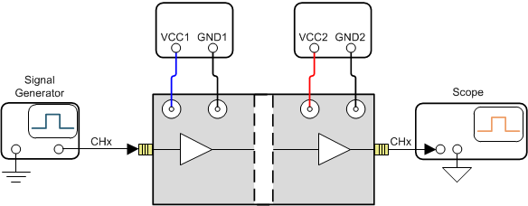
This section describes the setup and operation of the EVM for parameter performance evaluation. Figure 3-3 shows the configuration for operating the ISO6521 dual-channel functional isolator EVM using two power supplies.
 Figure 2-3 Basic EVM Operation
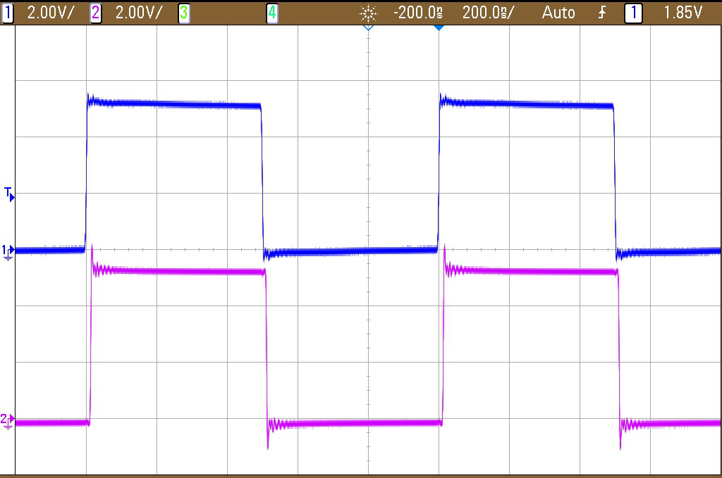
Figure 3-4 shows typical input and output waveforms of the EVM for a 1-MHz clock. The input is shown as channel 1, and the output is shown as channel 2.
 Figure 2-4 Typical Input and Output Waveform