SLOA101B August 2002 – May 2016 SN55HVD233-SEP , SN65HVDA1040A-Q1 , SN65HVDA1050A-Q1 , SN65HVDA540-5-Q1 , SN65HVDA540-Q1 , SN65HVDA541-5-Q1 , SN65HVDA541-Q1 , SN65HVDA542-5-Q1 , SN65HVDA542-Q1
-
Introduction to the Controller Area Network (CAN)
- Trademarks
- 1 Introduction
- 2 The CAN Standard
- 3 Standard CAN or Extended CAN
- 4 A CAN Message
- 5
The CAN Bus
- 5.1
CAN Transceiver Features
- 5.1.1 3.3-V Supply Voltage
- 5.1.2 ESD Protection
- 5.1.3 Common-Mode Voltage Operating Range
- 5.1.4 Common-Mode Noise Rejection
- 5.1.5 Controlled Driver Output Transition Times
- 5.1.6 Low-Current Bus Monitor, Standby and Sleep Modes
- 5.1.7 Bus Pin Short-Circuit Protection
- 5.1.8 Thermal Shutdown Protection
- 5.1.9 Bus Input Impedance
- 5.1.10 Glitch-Free Power Up and Power Down
- 5.1.11 Unpowered Node Protection
- 5.1.12 Reference Voltage
- 5.1.13 V-Split
- 5.1.14 Loopback
- 5.1.15 Autobaud Loopback
- 5.2 CAN Transceiver Selection Guide
- 5.1
CAN Transceiver Features
- 6 Conclusion
- 7 Additional Reading
- Revision History
5 The CAN Bus
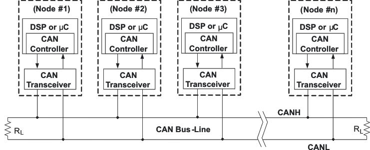
The data link and physical signaling layers of Figure 1, which are normally transparent to a system operator, are included in any controller that implements the CAN protocol, such as TI's TMS320LF2812 3.3-V DSP with integrated CAN controller. Connection to the physical medium is then implemented through a line transceiver such as TI's SN65HVD230 3.3-V CAN transceiver to form a system node as shown in Figure 6.
 Figure 6. Details of a CAN Bus
 Signaling is differential which is where CAN derives its robust noise immunity and fault tolerance. Balanced differential signaling reduces noise coupling and allows for high signaling rates over twisted-pair cable. Balanced means that the current flowing in each signal line is equal but opposite in direction, resulting in a field-canceling effect that is a key to low noise emissions. The use of balanced differential receivers and twisted-pair cabling enhance the common-mode rejection and high noise immunity of a CAN bus.
The High-Speed ISO 11898 Standard specifications are given for a maximum signaling rate of 1 Mbps with a bus length of 40 m with a maximum of 30 nodes. It also recommends a maximum unterminated stub length of 0.3 m. The cable is specified to be a shielded or unshielded twisted-pair with a 120-Ω characteristic impedance (Zo). The ISO 11898 Standard defines a single line of twisted-pair cable as the network topology as shown in Figure 6, terminated at both ends with 120-Ω resistors, which match the characteristic impedance of the line to prevent signal reflections. According to ISO 11898, placing RL on a node must be avoided because the bus lines lose termination if the node is disconnected from the bus.
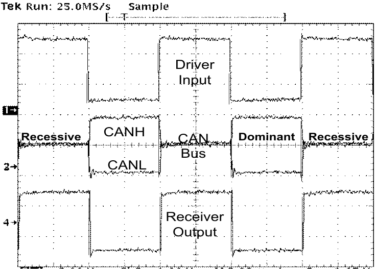
The two signal lines of the bus, CANH and CANL, in the quiescent recessive state, are passively biased to ≉ 2.5 V. The dominant state on the bus takes CANH ≉ 1 V higher to ≉ 3.5 V, and takes CANL ≉ 1 V lower to ≉ 1.5 V, creating a typical 2-V differential signal as displayed in Figure 7.
 Figure 7. CAN Dominant and Recessive Bus States
 The CAN standard defines a communication network that links all the nodes connected to a bus and enables them to talk with one another. There may or may not be a central control node, and nodes may be added at any time, even while the network is operating (hot-plugging).
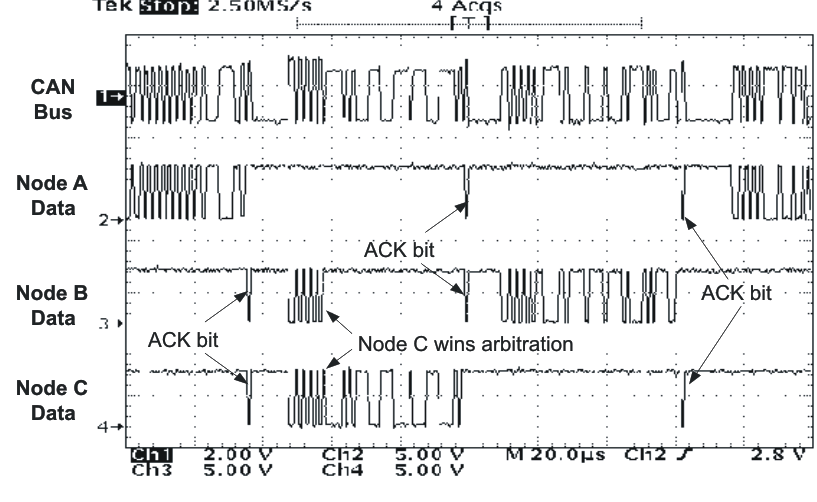
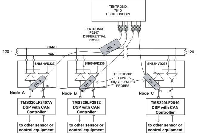
The nodes in Figure 8 and Figure 9 could theoretically be sending messages from smart sensing technology and a motor controller. An actual application may include a temperature sensor sending out a temperature update that is used to adjust the motor speed of a fan. If a pressure sensor node wants to send a message at the same time, arbitration ensures that the message is sent.
For example, Node A in Figure 8 and Figure 9 finishes sending its message (on the left side of Figure 8) as nodes B and C acknowledge a correct message being received. Nodes B and C then begin arbitration—node C wins the arbitration and sends its message. Nodes A and B acknowledge C's message, and node B then continues on with its message. Again note the opposite polarity of the driver input and output on the bus.
 Figure 8. CAN Bus Traffic
  Figure 9. CAN Test Bus