SLOA334 august 2023 DRV8955
1 Application Brief
Introduction
Whenever the flow of fluids or gases through a system needs to be controlled, magnetic valves, also known as solenoids can be used. A solenoid is a device that uses the magnetic properties of certain materials such as iron to open or close a valve.
A significant amount of power is consumed by the coil of the magnetic valve when operated with a constant current. The reason is that the power consumption of the coil is proportional to the current flow through it. To reduce the average current while still maintaining the correct operation of the valve, PWM can be used. By adjusting the duty cycle of the signal, the current can be controlled.
This document focuses on the operation of magnetic valves with PWM by using the DRV8955 and MSPM0 with IO-Link capabilities. Figure 1 shows how a typical system approach can be implemented.
 Figure 1 Typical System Approach
The TVS3301 acts as a bidirectional flat-clamp surge protection, the LM74500 is responsible for the reverse polarity protection and the TPSM365R6 is a 65-V input synchronous step-down DC/DC power module to generate the 3.3V.
PWM for Magnetic Valves
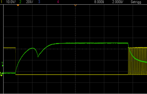
Figure 2 shows the current (green) and voltage (yellow, inverted) of controlling a magnetic valve. To make sure that the solenoid switched correctly, there is a short time without PWM control. As soon as the PWM signal started you can see the significant current drop through the magnetic valve.
 Figure 2 Current and Voltage Controlling
Magnetic Value
Figure 2 Current and Voltage Controlling
Magnetic ValueThe PWM frequency and duty cycle depends on the uses magnetic valve and the characteristics.
Using the DRV8955 to Control Magnetic Valves
The DRV8955 provides four individually controllable half-bridge drivers for industrial applications. The device can be used for driving up to four solenoid loads, two DC motors, one stepper motor, or other loads.
The output driver for each channel consists of N-channel power MOSFET’s configured in a half-bridge. A simple PWM (IN/IN) interface allows easy interface with the controller. Separate inputs to independently control each half-bridge are provided. Additionally, the outputs can be paralleled together to provide more current for output loads.
The DRV8955 operates off a single power supply and supports a wide input supply range from 4.5 V to 48 V. A low-power sleep mode is provided to achieve a low quiescent current draw by shutting down much of the internal circuitry. Internal protection functions are provided for undervoltage-lockout, overcurrent protection on each FET, short circuit protection, and overtemperature. Fault conditions are indicated by the nFAULT pin.
The application described in this document uses two DRV8955 to control up to 8 magnetic valves. To reduce the number of external components, the internal high-side FET can be used as a free-wheeling diode as you can see in Figure 3.
 Figure 3 Free-Wheeling Diode
To generate the PWM the MSPM0 is used. The advantage here is that the internal multiplexer can be used to route the timer signals to multiple pins. This also provides great flexibility for different valves because the parameters can be changed at any time.
Results
In the following there are different measurements with different duty cycles.
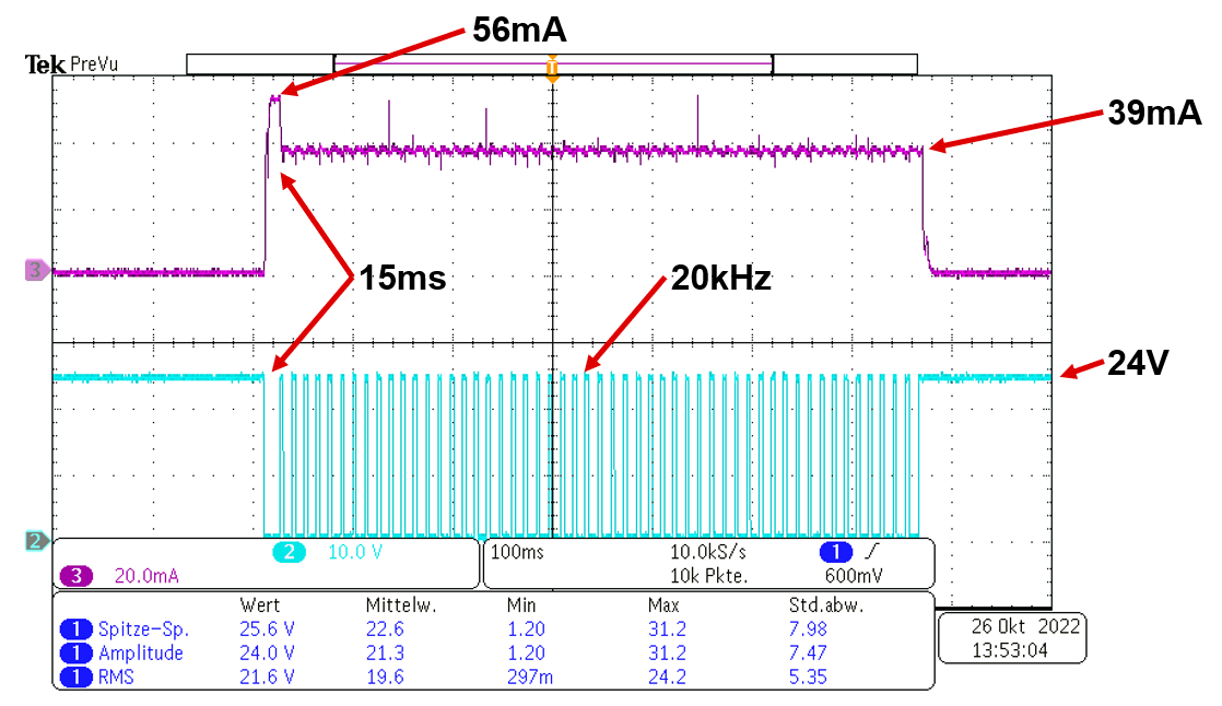
In Figure 4, a duty cycle of 70% is used to drive the solenoid. As shown, the peak current during the switch-on time is about 56 mA and after 15 ms it drops to 39 mA. That is a reduction of the current by around 30%.
 Figure 4 Peak Current During Switch-On Time
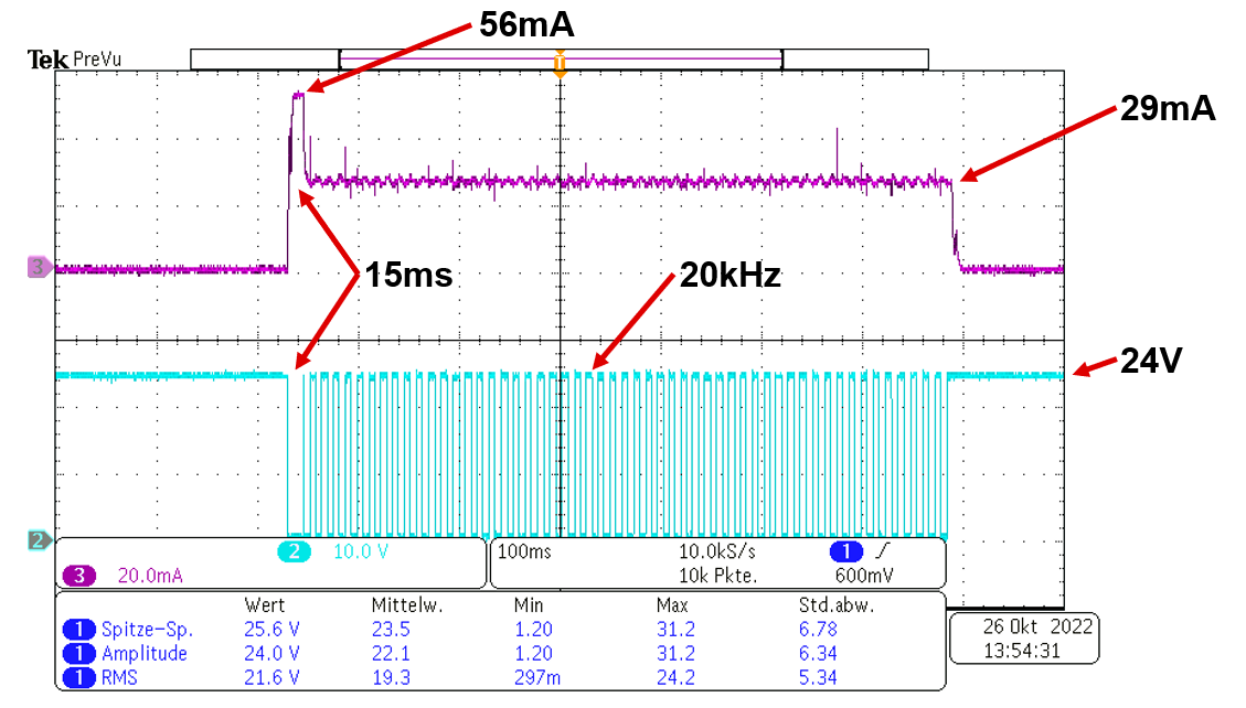
With a 50% duty cycle you can get a current reduction of about 48% as shown as in Figure 5.
 Figure 5 50% Duty Cycle
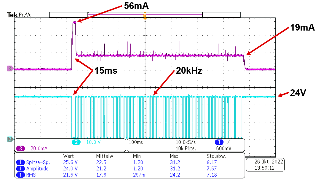
Figure 6 shows a 66% current reduction at a duty cycle of 30%.
 Figure 6 66% Current Reduction
It is important to select the correct duty cycle for the magnetic valve to reach a save operating environment. If the duty cycle is too low it can happen, that the valve does not switch correctly because of the reduced current through the coil.
Summary
This application brief shows how to control magnetic valves and solenoids using the DRV8955 as a driver and the MSPM0 as the PWM generator. Additionally, the application brief also shows the integration of IO-Link communication.
References and Related Parts
- Texas Instruments, DRV8955 Quad Half-Bridge Driver With Integrated Current Sense, data sheet.
- Texas Instruments, MSPM0G350x Mixed-Signal Microcontrollers With CAN-FD Interface, data sheet.
- Texas Instruments, TVS3301 33-V Bidirectional Flat-Clamp Surge Protection Device, data sheet.
- Texas Instruments, LM74500-Q1 Reverse Polarity Protection Controller, data sheet.
- Texas Instruments, TPSM365R6, 3-V to 65-V Input, 1-V to 13-V Output, 600-mA Synchronous Buck, data sheet.
- Texas Instruments, TIOL112 and TIOL112x IO-Link Device with Low Residual Voltage and Integrated Pro, data sheet.