SLOU579 August 2024 TSD5402-Q1
3.1.2 Using the PPC3 Plugin
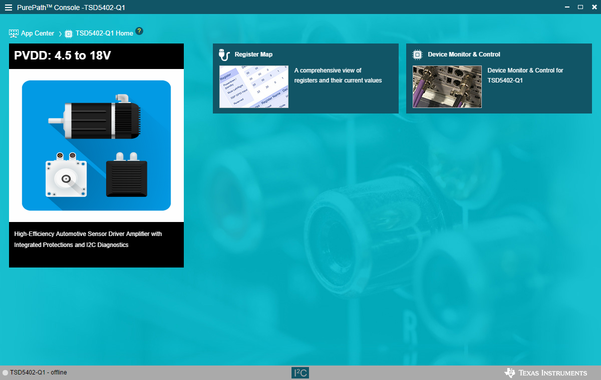
When the TSD5402 PPC3 is launched, the Home window is shown. If the EVM is powered on and the USB is connected to the PC, then the Home window displays Connect box in the bottom left hand corner. If the EVM is not powered on or the USB is not connected, then only TSD5402 – Offline is displayed.
 Figure 3-3 Home Window
There are two windows available with the TSD5402 PPC3 Home window: Register Map window and Device Monitor and Control window.
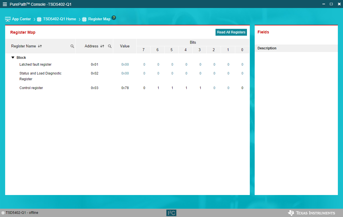
The Register Map window indicates the current settings off all the registers in the TSD5402-Q1. The left pane show the individual registers. The right pane shows the description of each bit in the chosen register. The control register values can be changed from this window.
 Figure 3-4 Register Map Window
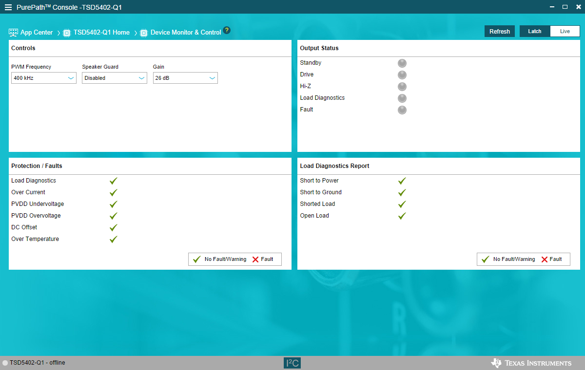
Click on the Device Monitor and Control Box on the Home window to display the Device Monitor and Control window. This window is a graphical representation of the register map. The Controls panes can be changed and the other panes indicated the values in the registers. The latch and live toggle buttons allows for the Output status, protection and load diagnostics to be static (latch) or dynamic (live). In Live mode, the I2C registers are being read continuously to refresh the panes.
 Figure 3-5 Device Monitor and Control
Window