SLUA450A January 2008 – November 2022 BQ27421-G1 , BQ27425-G2A , BQ27425-G2B , BQ27441-G1 , BQ27505-J2 , BQ27505-J3 , BQ27505-J4 , BQ27505-J5 , BQ27520-G4 , BQ27530-G1 , BQ27531-G1 , BQ27545-G1 , BQ27546-G1 , BQ27741-G1 , BQ40Z50 , BQ40Z50-R1 , BQ40Z50-R2
- Theory and Implementation of Impedance Track™ Battery Fuel-Gauging Algorithm in bq2750x Family
- Trademarks
- 1Summary of the Algorithm Operation
-
2Parameters Updated by the Gas Gauge in More Detail
- 2.1 Modes of Algorithm Operation
- 2.2 Update of Chemical Depth of Discharge (DOD)
- 2.3 Update of Qmax
- 2.4 Update of Resistance
- 2.5 Update of Temperature Model
- 2.6 Update of DataRAM.Remaining Capacity (RM) and DataRAM.Full Charge Capacity (FCC)
- 2.7 Update of DataRAM.Remaining Capacity( ) and DataRAM.State Of Charge( ) Values
- 3Real Application Example
- 4Revision History
2.6 Update of DataRAM.Remaining Capacity (RM) and DataRAM.Full Charge Capacity (FCC)
Update of RM and FCC takes place after each resistance grid-point update, at the end of discharge, and at the exit of relaxation mode.
FCC consists of three parts:
DataRAM.Full Charge Capacity( ) = Qstart+ PassedCharge + RM
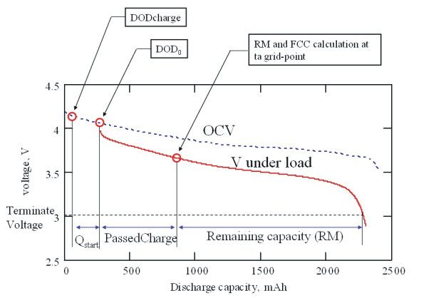
Components of FCC are indicated in an example in Figure 2-4.
 Figure 2-4 Components of DataRAM.Full Charge Capacity( ) Value
- Qstart is the charge that would have passed to make DOD = DOD0 from a fully charged state (DODcharge). For a fully charged battery Qstart = 0. Qstart is recalculated at the exit of relaxation mode. In the case of constant current, it is simply Qstart = Qmax × (DOD0 – DODcharge), but for the constant power case a voltage simulation is run. DODcharge is assigned equal to DOD0 at first DOD0 update after charge termination by taper current. Note that DODcharge is somewhat higher than 0 because chargers typically do not charge a battery to full.
- PassedCharge is the coulomb count integrated during the present discharge or charge and set to zero at every DOD0 update.
- Remaining capacity is calculated after each resistance grid-point update and at the end of discharge
DataRAM.Remaining Capacity( ) (RM) is calculated using a voltage simulation. The GG starts a simulation at the present DODstart = DOD0 + PassedCharge/Qmax and continues calculating voltage V(DODx,T) = OCV(DODx,T)+ I×R(DODx,T) by incrementing DOD with dDOD increment of 4%. DOD[i]=DODstart + dDOD×I. This incrementing is continued until the simulated voltage V(DOD[i]) becomes less than DF.Terminate Voltage. Once that happens, the final DOD is revealed. DataRAM.Remaining Capacity( ) = (DODfin-DODstart)×Qmax.
Current that is used in the simulation is the average current during the present discharge (several types of averaging can be selected using DF.Load Select data flash constant). A simulation can run in constant current mode (DF.Load Mode = 0) or constant power mode (DF.Load Mode = 1).