SLUA450A January 2008 – November 2022 BQ27421-G1 , BQ27425-G2A , BQ27425-G2B , BQ27441-G1 , BQ27505-J2 , BQ27505-J3 , BQ27505-J4 , BQ27505-J5 , BQ27520-G4 , BQ27530-G1 , BQ27531-G1 , BQ27545-G1 , BQ27546-G1 , BQ27741-G1 , BQ40Z50 , BQ40Z50-R1 , BQ40Z50-R2
- Theory and Implementation of Impedance Track™ Battery Fuel-Gauging Algorithm in bq2750x Family
- Trademarks
- 1Summary of the Algorithm Operation
-
2Parameters Updated by the Gas Gauge in More Detail
- 2.1 Modes of Algorithm Operation
- 2.2 Update of Chemical Depth of Discharge (DOD)
- 2.3 Update of Qmax
- 2.4 Update of Resistance
- 2.5 Update of Temperature Model
- 2.6 Update of DataRAM.Remaining Capacity (RM) and DataRAM.Full Charge Capacity (FCC)
- 2.7 Update of DataRAM.Remaining Capacity( ) and DataRAM.State Of Charge( ) Values
- 3Real Application Example
- 4Revision History
2.4 Update of Resistance
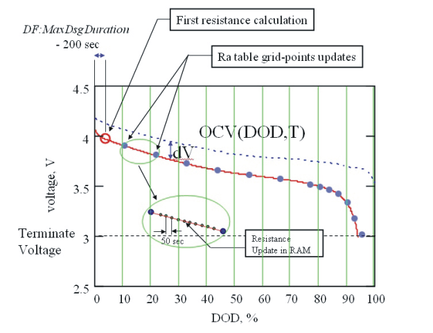
Resistance is updated during discharge, as summarized in Figure 2-3. The first resistance update happens after a certain waiting time to prevent distortion from transients after a load onset. The waiting time is 500 seconds by default, but later the update waiting time decreases if the maximal discharge duration (DF.Max Dsg Duration) is less than 500 seconds. The waiting time is defined as DF.Max Dsg Duration –200. Waiting time can decrease to as short as 100 seconds.
The calculation is performed by comparing the measured voltage with the OCV value at the same DOD, that is taken from the OCV(DOD,T) table:
dV = V – OCV(DOD,T)
R(DOD) = dV/I
Resistance measurements are taken continuously and stored in RAM.
Resistance is updated in the Data Flash (in DF.Ra Table) after each 11.1% of DOD charge is exceeded (DOD charge is PassedCharge/Qmax). When DOD reaches 77.7%, resistance is updated after each 3.3%. The final resistance update is made after discharge is terminated. .
The constant DF.Update Status increments by 1 when the first grid-point resistance update takes place (e.g., from 0 to 1 if no Qmax update were made before, or from 1 to 2 if a Qmax update was made before).
Before storage to Data Flash, the resistance values are normalized to 0°C as Ra[dod] = R[dod]/exp(Rb[dod]*T) where R is the measured resistance value at a given DOD. Rb[DOD] is the value of temperature coefficient of impedance change at a given DOD stored as a reserved data-flash table, and T is temperature in °C. Note that values of resistance normalized to 0°C are somewhat larger than values at room temperature and so cannot be directly compared with R=dV/I values.
 Figure 2-3 Impedance Updates
Resistance values for the grid points with a higher DOD than presently updated are scaled by the same factor as the present grid-point change, e.g., by factor Ra_new/Ra_old. In this way, faster convergence of the resistance profile is achieved.
Values in DF.Ra Table are stored in milliohm units, in the format DF.PackX Ra N where X is pack number from 0 to 1, and N is grid-point number from 0 to 14 that corresponds to 11.1% increments of DOD until 77.7%, and then 3.3% increments of DOD. In bq27500, there are two Ra tables (Ra and Rax) for each of the supported two battery packs. To save data-flash space, tables are compressed. Two additional parameters (Base R and Gain) are used in compression. The decompression formula for I=1..14 is
R[i] = Base R + sum(R_compressed[k], k = 1 .. I)×2Gain, and R[0]=Base R.
The DF.PackX Ra flag and DF.PackX Rax flag are used for interchanging data-flash column usage for reducing the number of DF writes. A flag value of 55 indicates the presently used data column, whereas FF indicates the presently unused data column.
Before DF.Update Status is set to 2, if during resistance update DOD exceeds 100%, or resistance appears negative, which are both indications of a too-small DF.Qmax Cellx initial guess, DF.Qmax Cell x will increment by 11.1%, and all resistances will be recalculated. This is normal behavior during the first learning cycle. However, if the initial guess of DF.Qmax Cell x was too far from the correct value, a second cycle might be needed to achieve full resistance accuracy. To avoid this, set DF.Qmax Cell x to a value specified by the cell manufacturer, multiplied by number of parallel cells.
After DF.Update Status is set to 2, resistance change is limited to below 5 times and above 0.2 times of its original value, and to positive values.