SLUAA69 July 2020 – MONTH TPS548D22
3.3 Choose an IC Supporting Pre-Bias Startup
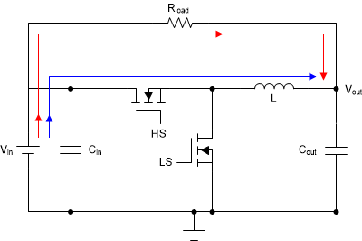
The pre-bias start-up condition occurs as a result of an external voltage present at the output of the power supply prior to its start up. This could be an issue for a synchronous converter because during start up the output will deliver power into the converter. The pre-bias start-up condition of buck with sinking current is shown in Figure 3-1.
 Figure 3-1 Pre-Bias Start-up Condition of Buck with
Sinking Current
Figure 3-1 Pre-Bias Start-up Condition of Buck with
Sinking CurrentDue to the soft-start logic of gradually increasing the duty cycle from zero to that required for regulation, the duty cycle is very small at the early time of soft-start. This means that the low-side MOSFET on time is much larger than the high-side MOSFET on time. When the low-side MOSFET turns on, it could sink large current from the output through the inductor path. This would result in a voltage drop on both the output and the input. If the input cannot provide a large inrush current the converter may go into UVLO and attempt to restart after release from UVLO. Finally, the converter may hiccup and get stuck in the start-up state. In the worst case, the system never starts at all.
Due to the soft-start logic of gradually increasing the reference voltage from zero to the target level, the feedback voltage at the inverting error amp input is much higher than the slow start reference voltage at the non-inverting input. This is because there already exists a voltage at the output. Hence, the control logic will try to decrease the duty cycle to discharge the pre-bias voltage at the output. This causes the low-side MOSFET to constantly turn on and the inductor current to negatively ramp up to a very large value. The constant large current may destroy the low-side MOSFET. Even with negative OCP, an OCP event could bring the converter into hiccup mode or latch-off mode. This means the converter still cannot escape from the start-up dilemma. Again, in the worst case, the system never starts at all.
To ensure the converter can start up normally, select devices such as TPS548B22 and TPS548D22 that support pre-bias start up. The principle behind pre-bias start up is that the device inhibits both high-side and low-side MOSFETs switching until the soft-start reference voltage ramps up and exceeds the feedback voltage. Inhibiting switching during the pre-bias start up condition gives no path for the output to discharge and conduct excessive large current. When the soft-start reference voltage exceeds the feedback voltage, the device begins to switch and start up from the pre-bias level.